
Fatigue test device for compression spring

A fatigue test, compression spring technology, applied in the direction of measuring device, testing of mechanical parts, testing of machine/structural parts, etc., can solve the problem of long fatigue test period of compression springs, and achieve simple structure, reasonable design and good economy. Effect

Active Publication Date: 2015-01-14
ANHUI HELI CO LTD
View PDF7 Cites 0 Cited by
  • Summary
  • Abstract
  • Description
  • Claims
  • Application Information

AI Technical Summary

Problems solved by technology

[0003] In order to solve the problem of long fatigue test period of the compression spring, the present invention does not use the cylinder driving mode, and provides a fatigue test device for the compression spring with good economy and manufacturability

Method used


Image

  • Fatigue test device for compression spring
  • Fatigue test device for compression spring
  • Fatigue test device for compression spring

Examples


Embodiment Construction

[0017] The present invention will be further described through the embodiments below in conjunction with the accompanying drawings.

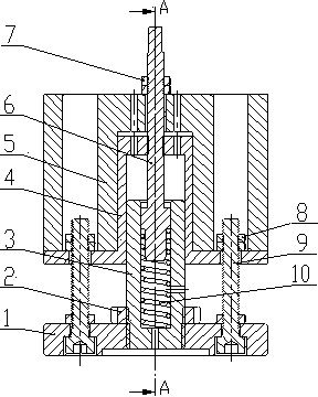
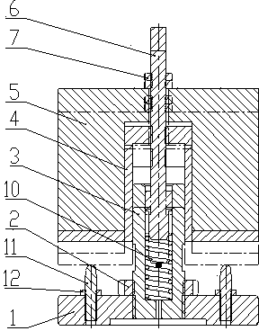
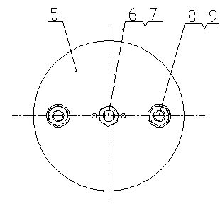
[0018] see figure 1 with image 3 , the fatigue test device for compression springs includes a circular base 1, the center of the base 1 is provided with an upright spring sleeve 3, the base 1 and the spring sleeve 3 are threaded, and the thread of the spring sleeve 3 A round nut 2 that plays a locking role is installed in conjunction with it. Two upright screw rods 9 and two upright limit screws 11 are evenly distributed on the circumference of the base 1, the two screw rods 9 are of equal height, and the two limit screws 11 are of equal height; and the height of the limit screw 11 is less than that of the screw rod 9 in height. The upper part of the spring sleeve 3 is covered with a cylindrical loading support 4, and the spring sleeve 3 is connected with a coaxial pre-tightening pressure rod 6 by threads, and the bottom of the pre-tightenin...


PUM


Abstract

The invention relates to a fatigue test device for a compression spring. A spring sleeve is arranged in the center of a base of the device; two threaded rods and two limiting screws are uniformly distributed on the periphery of the base; the heights of the limiting screws are less than those of the threaded rods; the upper part of the spring sleeve is sleeved with a loading support; a pretightening compression rod is arranged in the spring sleeve in a threaded connection manner; the lower part of the pretightening compression rod is in movable fit with the bore of the spring sleeve; the upper part of the pretightening compression rod extends out of the loading support; the outwards extending part is sleeved with a loading weight; the tops of the two limiting screws correspond to the bottom face of a seat plate of the loading support; the pretightening compression rod is adjusted to allow the loading support to move downwards; and when the bottom face of the seat plate of the loading support is contacted with the tops of the two limiting screws, the loading support stops moving downwards. With the adoption of the fatigue test device, a fatigue test cycle of the compression spring is shortened greatly; when a vibrating overweight loading mode is adopted for test, the set frequency is 20Hz, namely 20 times per second; and the tests only cost 27.8h when 2 million tests are conducted as required.

Description

technical field [0001] The invention belongs to the technical field of mechanical manufacturing, and in particular relates to a fatigue test device for a compression spring. Background technique [0002] At present, most compression spring fatigue tests are driven by cylinders, that is, when the piston rod of the cylinder is stretched out, the spring is compressed, and when the piston rod is retracted, the spring rebounds and resets. One cycle of piston rod expansion and contraction is counted as one compression spring test. This test method has the following defects: 1. The cylinder action response is relatively slow. At present, the action frequency of the test is generally 30 times / min. For the required test of 2 million times, the test only takes 1111.1h without considering the disassembly and inspection, that is, 46.3 Days, the test period is too long. 2. The manufacturability and economy of the test are poor. Contents of the invention [0003] In order to solve the...

Claims


Application Information

Patent Timeline
Patent Type & Authority Patents(China)
IPC IPC(8): G01M13/00
Inventor 代冠军刘红王军袁正张丽
Owner ANHUI HELI CO LTD
Learn More