
Liner supporting device provided with lengthened power spinning tube, supporting bars and ribbed plates

A technology of support device and support rod, which is applied in the fields of pressure vessel machinery, machinery, vehicle-mounted liquefied natural gas storage tank liner support machinery, and liner support device fields, can solve the problem of difficulty in achieving fatigue resistance, lack of scientific rationality, and temperature changes. Deformation and other problems, to achieve the effect of significant and reliable effect, scientific and reasonable design, and improved service life

Active Publication Date: 2013-03-20
BEIJING TIANHAI IND
View PDF8 Cites 0 Cited by
  • Summary
  • Abstract
  • Description
  • Claims
  • Application Information

AI Technical Summary

Problems solved by technology

[0002] At present, the inner tank of vehicle-mounted LNG is supported in the shell by the front and rear supports at both ends. The traditional support has the shortcomings, defects and disadvantages of simple structure and lack of scientific rationality, and it is difficult to achieve the strength corresponding to the actual road conditions in my country. Fatigue load requirements, that is, poor adaptability to external factors such as overload, vibration, shock, turbulence, anti-collision, and bad road conditions, resulting in poor thermal insulation effect, large heat conduction, and large heat loss during temperature changes. deformation, short service life, and even accidents

Method used


Image

  • Liner supporting device provided with lengthened power spinning tube, supporting bars and ribbed plates
  • Liner supporting device provided with lengthened power spinning tube, supporting bars and ribbed plates
  • Liner supporting device provided with lengthened power spinning tube, supporting bars and ribbed plates

Examples


Embodiment Construction

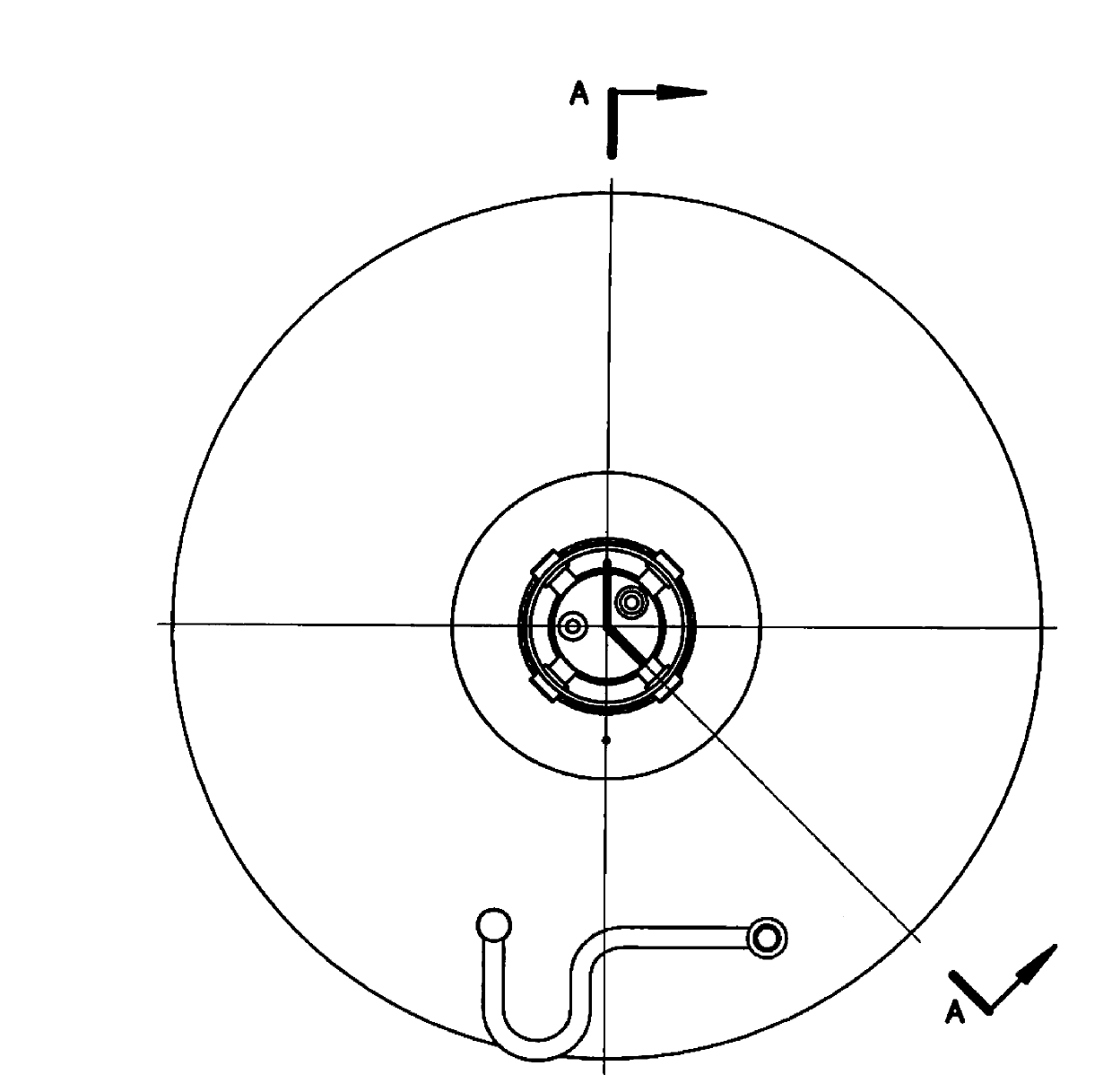
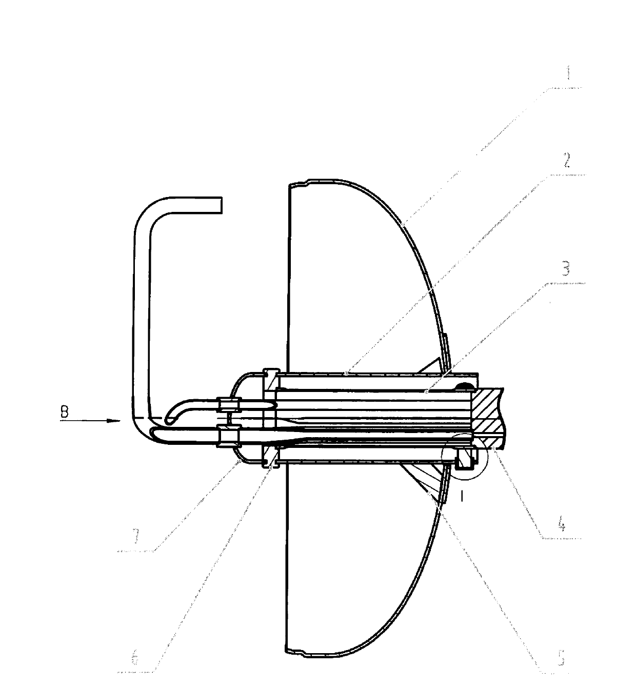
[0028] The present invention will be described in detail below in conjunction with the accompanying drawings. As shown in the accompanying drawings:

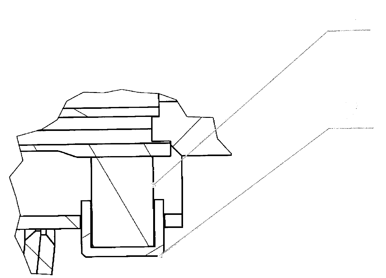
[0029] A liner support device provided with extended strong coils, support rods and ribs, consisting of a front head of the liner 1, a cylinder body 2, a strong coil 3, a manifold valve seat 4, ribs 5, and a support ring 6 , head 7, inflation pipe 8, vent pipe 9, liquid outlet pipe 10, support rod 11, support rod end cover 12;

[0030] In the liner support device provided with extended strong coils, support rods and ribs, the center hole of the front head 1 of the liner and the outer end section of the cylinder 2, the inner end of the cylinder 2 and the support ring 6 One side, the other side of the support ring 6 and the head 7, one side of the support ring 6 and the inner end of the strong coil 3, the outer end of the strong coil 3 and the manifold valve seat 4, one end of the rib plate 5 and the cylinder body 2 while the ot...


PUM


Abstract

The invention provides a liner supporting device provided with a lengthened power spinning tube, supporting bars and ribbed plates, relating to the technical field of machinery. With the key technology of providing the lengthened power spinning tube, the supporting bars and the ribbed plates, the device is characterized in that the center hole of a liner front head is fixedly connected with the outer end section of a barrel; the inner end of the barrel is fixedly connected with one side of a support ring; the other side of the support ring is fixedly connected with a head; one side of the support ring is also fixedly connected with the inner end of the power spinning tube; the outer end of the power spinning tube is fixedly connected with a manifold valve seat; one ends of the ribbed plates are fixedly connected with the barrel and the other ends of the ribbed plates are fixedly connected with the inner wall of the liner front head; the inner end sections of a gas filled tube, a blow-down tube and an outlet tube pass through and are fixedly connected with tube holes on the support ring and then pass through and are fixedly connected with tube holes on the head; the outer end sections of the three tubes pass through and are fixedly connected with tube holes on the manifold valve seat; a supporting bar end cover hole on the outer end section of the barrel is fixedly connected with a supporting bar end cover; the supporting bar end cover is connected with one ends of the supporting bars in an inlaid manner; and the other ends of the supporting bars are connected with the outer end section of the power spinning tube through push-pressing. The device is used for fixing the liner, has goof fixing effect and reduces heat losses.

Description

technical field [0001] The invention is provided with a liner supporting device with an extended strong coil, a support rod and a rib, and relates to the field of mechanical technology; in particular, it relates to the field of mechanical technology of pressure vessels; in particular, it relates to the field of mechanical technology for supporting the liner of a vehicle-mounted liquefied natural gas storage tank; specifically It relates to the technical field of an inner tank support device provided with an extended strong coil, a support rod and a rib plate. Background technique [0002] At present, the inner tank of vehicle-mounted LNG is supported in the shell by the front and rear supports at both ends. The traditional support has the disadvantages of simple structure and lack of scientific rationality, defects and disadvantages, and it is difficult to achieve the strength corresponding to the actual road conditions in my country Fatigue load requirements, that is, poor a...

Claims


Application Information

Patent Timeline
Patent Type & Authority Applications(China)
IPC IPC(8): F17C13/00F17C13/06
Inventor 吕兴民石凤文张增营李兆亭刘宇赵剑
Owner BEIJING TIANHAI IND
Learn More