Arbitrary-tooth difference rolling transmission internal combustion engine

A technology of internal combustion engine and transmission mechanism, applied in the direction of transmission, machine/engine, mechanical equipment, etc., can solve the problems of shortening the life of the internal combustion engine, difficulty in processing, manufacturing, assembly, large mechanical wear, etc. Simple, consistent, compact results

Inactive Publication Date: 2015-04-22
SICHUAN UNIV
View PDF6 Cites 0 Cited by
  • Summary
  • Abstract
  • Description
  • Claims
  • Application Information

AI Technical Summary

Problems solved by technology

Since this kind of internal combustion engine relies on the linear motion of the piston and the plane motion of the connecting rod to press and drive the crankshaft to rotate, there is a large friction between the motion pairs, resulting in low transmission efficiency of the internal combustion engine.
These existing crankshaft connecting rod type internal-combustion engines also have the following main disadvantages: large volume; the unbalanced centrifugal force on the connecting rod and crankshaft is relatively large; the impact is large and the vibration is large; The structure is complex, and it is difficult to process, manufacture, and assemble; in addition, the general internal combustion engine and the transmission device are two independent machines, and usually the internal combustion engine needs to be installed with a transmission for subsequent transmission, resulting in a large volume

Method used


Image

  • Arbitrary-tooth difference rolling transmission internal combustion engine
  • Arbitrary-tooth difference rolling transmission internal combustion engine
  • Arbitrary-tooth difference rolling transmission internal combustion engine

Examples


Embodiment Construction

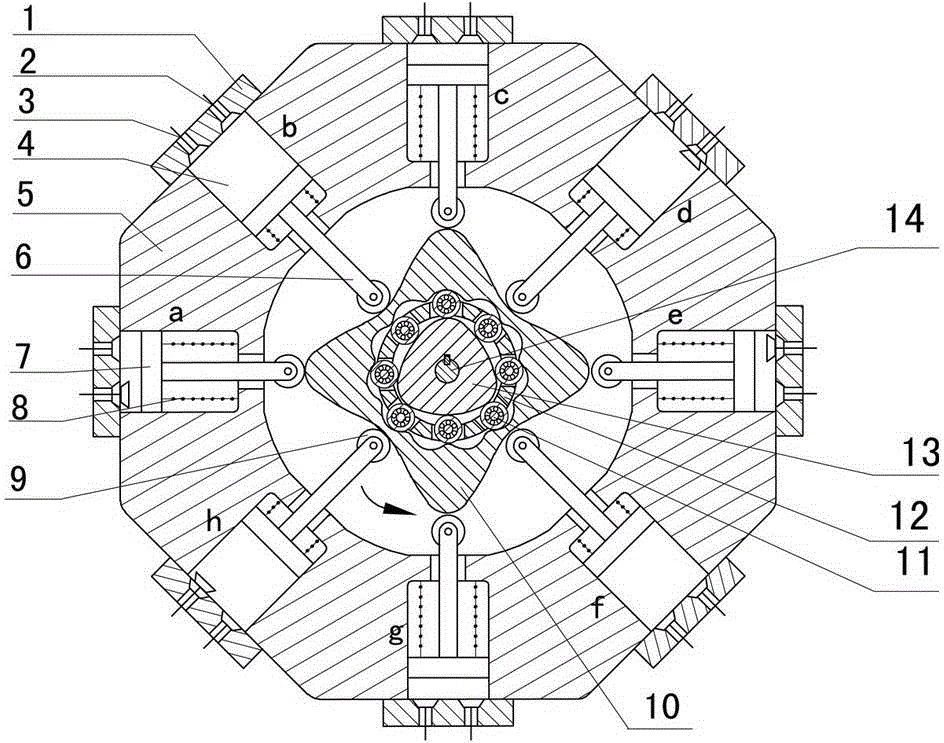
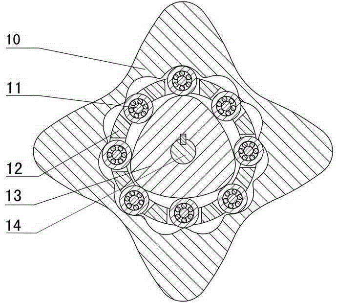
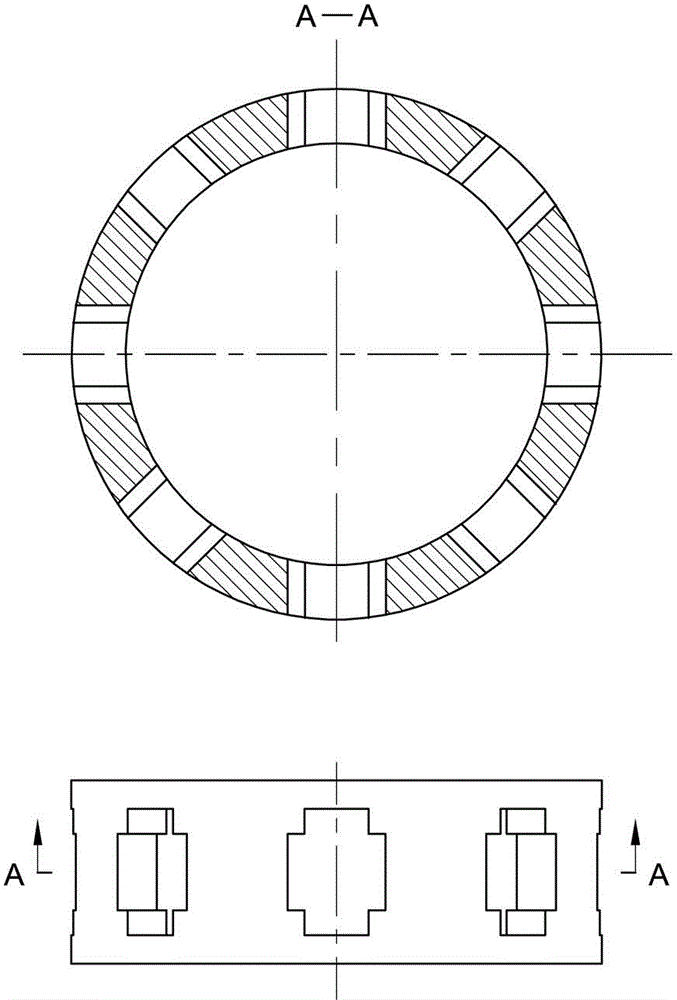
[0041] Figure 1 to Figure 5 The rolling transmission internal combustion engine with any number of tooth differences shown is composed of cylinder head (1), exhaust valve (2), intake valve (3), cylinder (4), cylinder block (5), push rod (6), piston (7), spring (8), roller (9), convex inner ring gear (10), rolling movable tooth (11), movable gear rack (12), multi-phase external cam (13), output shaft ( 14) Etc. composition. The eight cylinders (4) are evenly distributed around the convex inner ring gear (10) in an axially symmetrical manner, and the angle between two adjacent cylinders is 45°. There is a piston (7) in each cylinder (4), and one end of the push rod (6) is consolidated with the piston (7), and the other end is equipped with a roller (9), and the roller (9) makes the push rod ( 6) The connection with the convex inner ring gear (10) is a rolling friction connection. One end of the spring (8) is fixed on the bottom of the piston (7), and the other end is fixed on...


PUM


Abstract

The invention discloses an arbitrary-tooth difference rolling transmission internal combustion engine, and relates to the field of gas power. According to a novel internal combustion engine, eight cylinders are annularly, symmetrically and uniformly distributed around an outer cam inner gear ring, so that resultant force on the outer cam inner gear ring is zero; and pistons of the cylinders directly act on the outer cam inner gear ring through pushrods, and power is transmitted to an output shaft in key connection with a multi-phase outer cam in a multi-phase outer cam impact wave rolling oscillating tooth transmission way through the outer cam inner gear ring. According to the internal combustion engine, a connecting rod and a crankshaft in the conventional internal combustion engine are eliminated, a multi-phase outer cam impact wave rolling transmission mechanism has the characteristics of no eccentric mass and self-balance of inertia force and a working load, the rotating speed of the output shaft is determined by the transmission ratio of oscillating teeth, and if an oscillating tooth rack is fixed, the output of the multi-phase outer cam is realized at high speed. The internal combustion engine can be widely applied to fields with requirements on high rotating speed, such as a helicopter engine and a miniature generator, and when the output rotating speed is fixed, the emissions of harmful gases can be reduced. The internal combustion engine is simple and compact in structure and small in axial size, has a force self-balancing function, and can run stably.

Description

technical field [0001] The invention relates to the field of gas power, more specifically, a rolling transmission internal combustion engine with any number of tooth differences. Background technique [0002] At present, a general internal combustion engine (engine) is composed of a body, a crank connecting rod mechanism, a gas distribution mechanism, a cooling system, a lubrication system, a fuel system, and an ignition system. stroke. The transmission mechanism of this type of internal combustion engine uses a crank-connecting rod mechanism, which transmits the power of the piston to the crankshaft through the connecting rod, and converts the reciprocating linear motion of the piston into the rotary motion of the crankshaft. Because this internal combustion engine presses and drives the crankshaft to rotate by the linear motion of the piston and the planar motion of the connecting rod, there is greater friction between the kinematic pairs, resulting in low transmission ef...

Claims


Application Information

Patent Timeline
Patent Type & Authority Patents(China)
IPC IPC(8): F02B75/40F16H37/12
Inventor 梁尚明贺飞飞
Owner SICHUAN UNIV
Why Eureka
Try Eureka