Fluidization cabinet type delivery pump and method thereof

A fluidization and conveying pump technology, used in conveyors, conveying bulk materials, transportation and packaging, etc., can solve the problems of weakened sealing performance, slow fluidization speed of a single intake, environmental pollution, etc., to achieve enhanced sealing ability. Effect

Active Publication Date: 2013-03-20
ZHEJIANG GUTE PNEUMATIC MACHINERY
View PDF9 Cites 4 Cited by
  • Summary
  • Abstract
  • Description
  • Claims
  • Application Information

AI Technical Summary

Problems solved by technology

[0004] The current fluidized silo-type delivery pumps all adopt a single air intake system on the air intake. The single air intake has defects such as slow fluidization speed and unadjustable solid-gas ratio, so the storage capacity is poor, the delivery pressure fluctuates greatly, Problems such as pipeline movement; Existing equipment is usually sealed with external force, and the sealing force is constant. When the pressure in the pump body increases, the sealing performance is weakened, which is prone to leakage, causing environmental pollution and equipment wear and other problems; existing The fluidizer of the equipment usually adopts a porous fluidizing disc, which leads to large air flow dead angle and uneven fluidization in the pump body, and the fluidization holes are easy to block, poor reliability, high energy consumption, low efficiency, and high flow rate.

Method used


Image

  • Fluidization cabinet type delivery pump and method thereof
  • Fluidization cabinet type delivery pump and method thereof
  • Fluidization cabinet type delivery pump and method thereof

Examples


Embodiment Construction

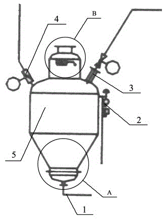
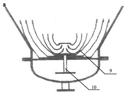
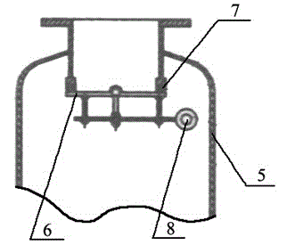
[0016] Such as figure 1 , 2 , 3, the fluidized silo-type conveying pump includes a main air intake device 1, a secondary air intake device 2, a tertiary air intake device 3, a ventilation device 4, a pump body 5, a feeding device, and a fluidization device; the pump body 5. There is a main air intake device 1 outside the bottom of the pump body 5. A fluidization device is provided inside the bottom of the pump body 5. A secondary air intake device 2 is provided on the outer wall of the middle part of the pump body 5. A tertiary air intake device is provided on the top of the pump body 5. 3. Ventilation Device 4, feeding device; the feeding device includes a cover plate 6, a sealing gasket 7, and a rotating shaft 8, the cover plate 6 is rotatably connected to the pump body 5 through the rotating shaft 8, and the opening between the cover plate 6 and the pump body 5 passes through the sealing gasket 7 Sealing; a fluidization device is provided in the bottom of the pump body 5, ...


PUM


Abstract

The invention discloses a fluidization cabinet type delivery pump and a method of the fluidization cabinet type delivery pump. The fluidization cabinet type delivery pump and the method of the fluidization cabinet type delivery pump comprise a main air inlet device, a secondary air inlet device, a tertiary air inlet device, a ventilation device, a pump body, a cover plate, a sealing pad, a rotating shaft, a multi-layer vulcanization disc and a voltage divider and is suitable for pneumatic transportation of fly ash. The main air inlet device is arranged at the bottom of the pump body and is communicated with the pump body in a controllable mode. The secondary air inlet device is arranged in the middle of the pump body and is communicated with the pump body in a controllable mode. The tertiary air inlet device and a ventilation hole are arranged on the top of the pump body and are communicated with the pump body in a controllable mode. The cover plate which is arranged at the top end of the pump body is connected with the pump body through the rotating shaft and the sealing pad in a sealing mode. The multi-layer vulcanization disc and the voltage divider which are arranged at the bottom end of the pump body are connected with the pump body in sequence. The fluidization cabinet type delivery pump and the method of the fluidization cabinet type delivery pump solve the problems of the existing devices of being small in ash air inlet ratio, high in energy consumption, low in efficiency, high in current speed, poor in sealing, big in fluctuating of transporting pressure, serious in pipe movement and the like. The fluidization cabinet type delivery pump and the method of the fluidization cabinet type delivery pump have the advantages of being big in system force contribution, long in delivery distance, high in ash air ratio, low in energy consumption, high in vulcanization rate, stable in transporting pressure, wide in application range, good in sealing and the like.

Description

technical field [0001] The invention relates to a pneumatic conveying device, in particular to a fluidized bin-type conveying pump and a method thereof. Background technique [0002] my country has abundant coal resources, so coal-fired power generation has always been the main power construction in my country, which has led to a sharp increase in the emission of fly ash. Fly ash is solid particles produced during the combustion process of coal-fired boilers, and is a by-product of coal combustion in thermal power plants. Fly ash includes fly ash collected by dust collectors and slag discharged from the furnace bottom (commonly known as bottom ash). The part of the fly ash that is not captured by the dust collector enters the large air intake and becomes suspended particles polluted by coal-fired air intake, which is extremely harmful to the environment and difficult to deal with. Because fly ash belongs to fine particle dust, it has the characteristics of high dispersi...

Claims


Application Information

Patent Timeline
IPC IPC(8): B65G53/50B65G53/16
Inventor 叶一舟叶建山刘宇澄
Owner ZHEJIANG GUTE PNEUMATIC MACHINERY
Why Eureka
Try Eureka