Laser machining device based on ultrasonic location and machining method

A laser processing method and laser processing technology, applied in laser welding equipment, metal processing equipment, manufacturing tools, etc., can solve problems that affect welding or cutting quality, workpiece does not meet requirements, changes, etc., to improve processing efficiency and processing accuracy , to avoid cumbersome effects

Active Publication Date: 2013-03-20
INST OF SEMICONDUCTORS - CHINESE ACAD OF SCI
View PDF6 Cites 8 Cited by
  • Summary
  • Abstract
  • Description
  • Claims
  • Application Information

AI Technical Summary

Problems solved by technology

[0002] When using a laser to process a workpiece, the position of the laser spot is generally determined by a helium-neon laser, especially when welding or cutting a larger workpiece, such as tailor welding of a large plate, because the plate surface cannot be guaranteed to be flat, which will cause laser During the welding process, the defocus of laser welding parameters changes, which requires the operator to measure the height of the laser head after a period of time, so as to prevent a large change in the defocus, which will deteriorate the welding performance and make the processed The workpiece does not meet the requirements. At present, a ruler is used to measure the distance between the workpiece and the lens to calculate the defocus amount. This is a large workload, and there are also large differences between multiple measurements, resulting in welding or cutting. The decrease in precision greatly affects the quality of welding or cutting. At present, there is an urgent need for a system that can automatically adjust the distance between the laser processing head and the surface of the workpiece, which can greatly reduce the workload and improve production efficiency and processing accuracy.

Method used


Image

  • Laser machining device based on ultrasonic location and machining method
  • Laser machining device based on ultrasonic location and machining method

Examples


Embodiment Construction

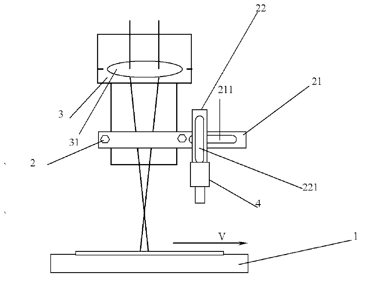
[0018] see figure 1 As shown, the present invention provides a laser processing device based on ultrasonic positioning, including:

[0019] A processing platform 1;

[0020] A clamping device 2, which is located above the processing platform 1, the clamping device 2 includes a transverse clamping connection part 21 and a longitudinal clamping connection part 22, and the horizontal clamping connection part 21 and the longitudinal clamping connection part 22 are pivoted to each other Then, there is a transverse sliding groove 211 on the transverse clamping connection part 21 of the clamping device 2, which facilitates the sliding of the longitudinal clamping connection part 22 of the clamping device 2, and there is a longitudinal clamping connection part 22 on the clamping device 2 The longitudinal chute 221 facilitates the sliding of the ultrasonic distance measuring device 4 pivotally connected to the longitudinal clamping connection part 22 of the clamping device 2;

[0021...


PUM


Abstract

The utility model provides a laser machining device based on an ultrasonic location and a machining method. The laser machining device based on the ultrasonic location comprises a machining platform, a clamping device, a laser head and an ultrasonic range-measurement device, wherein the clamping device arranged above the machining platform comprises a transverse clamping connecting part and a longitudinal clamping connecting part, the transverse clamping connecting part and the longitudinal clamping connecting part are connected with each other in a pivot mode, the laser head is in pivot connection with the transverse clamping connecting part of the clamping device and arranged above the machining platform, and the ultrasonic range-measurement device is in pivot connection with the longitudinal clamping connecting part of the clamping part. The laser machining device based on the ultrasonic location can guarantee laser machining quality, improves machining accuracy, and can fast and conveniently confirm change situations of defocusing amount during machining.

Description

technical field [0001] The invention relates to a laser processing head, in particular to a laser processing device and processing method based on ultrasonic positioning. Background technique [0002] When using a laser to process a workpiece, the position of the laser spot is generally determined by a helium-neon laser, especially when welding or cutting a larger workpiece, such as tailor welding of a large plate, because the plate surface cannot be guaranteed to be flat, which will cause laser During the welding process, the defocus of laser welding parameters changes, which requires the operator to measure the height of the laser head after a period of time, so as to prevent a large change in the defocus, which will deteriorate the welding performance and make the processed The workpiece does not meet the requirements. At present, a ruler is used to measure the distance between the workpiece and the lens to calculate the defocus amount. This is a large workload, and there...

Claims


Application Information

Patent Timeline
IPC IPC(8): B23K26/04B23K26/20B23K26/042B23K26/21
Inventor 赵伟芳林学春于海娟李晋闽
Owner INST OF SEMICONDUCTORS - CHINESE ACAD OF SCI
Why Eureka
Try Eureka