Reaction device for SNCR (selective non-catalytic reduction) denitration system of circulating fluid bed

A circulating fluidized bed and reaction device technology, applied in chemical instruments and methods, dispersed particle separation, lighting and heating equipment, etc., can solve the problems of SNCR system inoperability, increased reductant escape, and reduced denitrification reaction speed, etc. Achieve normal operation, good escape, and reduce temperature fluctuations

Inactive Publication Date: 2013-03-20
江苏百灵天地环境设计研究院有限公司
View PDF4 Cites 9 Cited by
  • Summary
  • Abstract
  • Description
  • Claims
  • Application Information

AI Technical Summary

Problems solved by technology

When the boiler load decreases, the flue gas temperature in the cyclone separator decreases. When the flue gas temperature decreases with the load and is lower than the minimum limit of the SNCR optimal reaction temperature range, the denitrification reaction speed decreases, and the escape amount of the reducing agent increases. The flue gas emission measurement NH X Emission exceeding the standard, NH 3 Emissions exceed the standard, which eventually leads to the failure of the SNCR system to operate
When the boiler load increases, the flue gas temperature in the cyclone separator rises. When the flue gas temperature increases with the load and is higher than the maximum limit of the SNCR optimal reaction temperature range, NH 3 Oxidation reactions play a dominant role over reduction reactions, which can also cause NH X Emission exceeding the standard, NH 3 Exceeding the emission standard, the SNCR system cannot operate

Method used


Image

  • Reaction device for SNCR (selective non-catalytic reduction) denitration system of circulating fluid bed
  • Reaction device for SNCR (selective non-catalytic reduction) denitration system of circulating fluid bed
  • Reaction device for SNCR (selective non-catalytic reduction) denitration system of circulating fluid bed

Examples


Embodiment Construction

[0022] The technical solution of the present invention will be described in detail below in conjunction with the accompanying drawings: the description in this part is only exemplary and explanatory, and should not have any limiting effect on the protection scope of the invention.

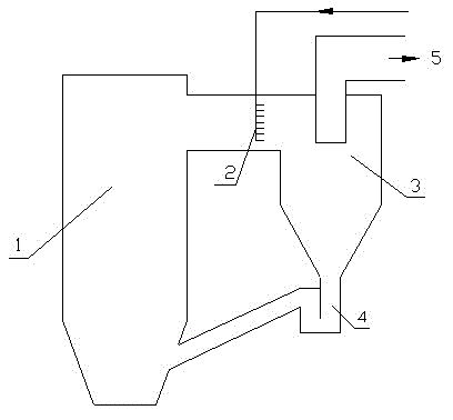
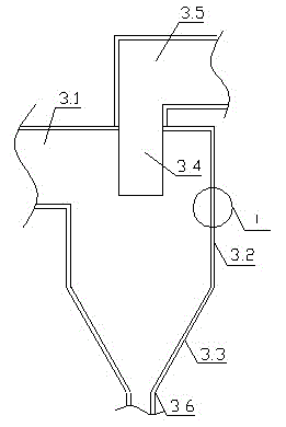
[0023] like figure 1 , figure 2 As shown, a reaction device for circulating fluidized bed SNCR denitrification system, including circulating fluidized bed boiler 1, horizontal flue, return device 4, tail flue 5, one side of circulating fluidized bed boiler 1 respectively It is connected with one end of the horizontal flue and the return device 4, the tail flue 5 is arranged at the other end of the horizontal flue, and the cyclone separator 3 is arranged between the other end of the horizontal flue and the return device 4, and the cyclone separator 3 Including air inlet 3.1, cylinder body 3.2, cone body 3.3, central cylinder 3.4, exhaust port 3.5, discharge port 3.6, the upper side of cylinder bod...


PUM


Abstract

The invention discloses a reaction device for an SNCR (selective non-catalytic reduction) denitration system of a circulating fluid bed, and relates to a smoke denitration reactor in a power plant. The reaction device provided by the invention is characterized in that one side of a circulating fluid bed boiler is connected with one ends of a horizontal flue and a material returning device respectively, the other end of the horizontal flue is provided with a tail flue, and a cyclone separator is arranged between the other ends of the horizontal flue and the material returning device; one side of the upper part of a cylinder body is provided with an air inlet connected with the horizontal flue, a center cylinder connected with one end of an exhaust port is arranged at the upper part of the cylinder body, the other end of the exhaust port is connected with the tail flue, the lower part of the cylinder body forms a cone which is gradually shrunken, one end, which is far from the cylinder body, of the cone is provided with a discharge port, and the tail end of the discharge port is connected with the material returning device; and a phase change heat storage material layer is arranged on the inner wall of the cylinder body. The reaction device provided by the invention can well control the escape quantity of a reducing agent, has wide load range of the boiler, can meet the discharage of NOX with high requirements, and realizes the purpose that the SNCR system runs normally.

Description

[0001] technical field [0002] The invention relates to a flue gas denitrification reactor of a power plant, in particular to a cyclone separator suitable for a flue gas SNCR denitrification system of a circulating fluidized bed boiler, and belongs to the technical field of flue gas purification device manufacturing. [0003] Background technique [0004] Circulating fluidized bed combustion technology (CFB) is a high-efficiency, low-pollution and clean combustion technology developed rapidly in the past ten years. It has strong adaptability to coal types, large load adjustment range, stable combustion, and low cost of adding limestone in the furnace Desulfurization, staged combustion effectively reduce NOx emissions, comprehensive utilization of ash, etc., especially suitable for peak-shaving power plants that burn inferior fuels and frequently change loads and self-provided power plants with large load fluctuations. [0005] According to the "Emission Standards of Air Po...

Claims


Application Information

Patent Timeline
Patent Type & Authority Applications(China)
IPC IPC(8): B01D53/78B01D53/56F23J15/04
Inventor 卢作基秦翠娟代旭东钟学进陈凯
Owner 江苏百灵天地环境设计研究院有限公司
Why Eureka
Try Eureka