Clamping and moving device and method of cross beam of horizontal type tensile and compression testing machine

A technology of mobile devices and testing machines, which is applied in the direction of measuring devices, instruments, scientific instruments, etc., can solve the problems of large adjustment test space, large push-pull cylinder stroke, and increased manufacturing cost of testing machines, so as to achieve convenient operation and occupy space on the site small effect

Inactive Publication Date: 2013-03-13
JINAN SHIDAI SHIJIN TESTING MACHINE GRP
View PDF8 Cites 3 Cited by
  • Summary
  • Abstract
  • Description
  • Claims
  • Application Information

AI Technical Summary

Problems solved by technology

For some large materials or structural parts, a testing machine that can adjust the test space to a large extent is needed to perform tension, compression or fatigue tests on materials or components, such as horizontal tension and compression testing machines. The crossbeam (moving beam) needs to adjust the test space at any time according to the length of the test piece. For large horizontal tensile and compression testing machines, the crossbeam is generally fixed by a bolt structure or a bolt fastening structure. The former fixing method requires a bolt hole. There is a certain interval, so it cannot be adjusted steplessly in the entire test space of the testing machine. The latter fixing method requires manual operation and cannot be clamped and fixed automatically; and for the movement of the beam, chain drive, rack and pinion drive are usually used , or hydraulic cylinder push-pull, the first two movement methods need to design a special transmission system, which cannot make full use of the hydraulic system of the testing machine itself; the latter movement method requires a large-stroke hydraulic cylinder or multi-stage hydraulic cylinder, which is realized by pushing and pulling the beam. Position adjustment, but due to the large adjustment test space, the large-stroke hydraulic cylinder will occupy a large space after being installed on both sides of the testing machine. Although the multi-stage cylinder occupies a small space, the production requirements of the hydraulic cylinder are high. Will increase the manufacturing cost of the testing machine
[0003] figure 2 and image 3 For two embodiments of the prior art, figure 2 The movement and fixation of the crossbeam shown adopt the common way of motor, rack drive and pin fixation; image 3 The movement of the crossbeam shown in the figure uses push-pull cylinders fixed on both sides of the frame to realize the movement of the crossbeam. Due to the large stroke of the push-pull cylinder, it will occupy a large space after being installed on both sides of the testing machine.

Method used


Image

  • Clamping and moving device and method of cross beam of horizontal type tensile and compression testing machine
  • Clamping and moving device and method of cross beam of horizontal type tensile and compression testing machine
  • Clamping and moving device and method of cross beam of horizontal type tensile and compression testing machine

Examples


Embodiment Construction

[0015] The present invention will be specifically described below in conjunction with the accompanying drawings and embodiments.

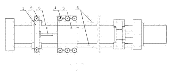
[0016] figure 1 It is a structural schematic diagram of the present invention.

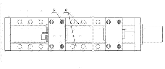
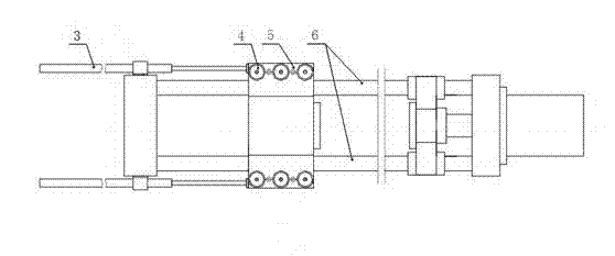
[0017] In order to realize the clamping and fixing of the crossbeam 5, the present invention includes a column 6, a crossbeam 5 and a crossbeam clamping cylinder 4, and multiple sets of crossbeam clamping cylinders 4 are installed on the four corners of the crossbeam 5, and the crossbeam clamping cylinder on each corner 4 is responsible for the fixing of this position and the column 6. When the beam clamping cylinder 4 is clamped, the beam 5 is fixed on the column 6. When the beam clamping cylinder 4 is loosened, the beam 5 is loosened by its own elasticity. At this time, the beam 5 can move along the column 6 after being acted by external force.

[0018] In order to realize the movement of the beam 5 , the present invention also includes a fixed plate 1 , a clampin...


PUM


Abstract

The invention discloses a clamping and moving device and method of a cross beam of a horizontal type tensile and compression testing machine. The device comprises a column, the cross beam and cross beam clamping cylinders, wherein the cross beam clamping cylinders are installed on the four corners of the cross bean; and the cross beam is clamped or released from the column through the cross beam clamping cylinders. The device further comprises a push-pull oil cylinder, a fixing plate and fixing plate clamping cylinders, wherein the fixing plate is arranged in parallel to the cross beam; the fixing plate is clamped or released from the column through the fixing plate clamping cylinders; the push-pull oil cylinder is arranged inside a frame and positioned between the cross beam and the fixing plate; the push-pull oil cylinder is a double action hydraulic cylinder; the piston and the cylinder barrel of the push-pull oil cylinder are respectively linked with the cross beam and the fixing plate; and hydraulic oil paths of the fixing plate clamping cylinders, the push-pull oil cylinder and the cross beam clamping cylinders are switched under electric control so as to clamp, release and move along the column in a stepless adjustment mode. By combining cross beam hydraulic clamping and hydraulic pushing, the resource of a testing machine is sufficiently utilized, occupied field is small and operation is convenient.

Description

technical field [0001] The invention relates to a clamping and moving device for a beam of a testing machine, in particular to a clamping and moving device for a beam of a horizontal tensile and compression testing machine with relatively large test space adjustment. Background technique [0002] With the progress and development of society, testing machines are used more and more widely as equipment for material testing and testing. For some large materials or structural parts, a testing machine that can adjust the test space to a large extent is needed to perform tension, compression or fatigue tests on materials or components, such as horizontal tension and compression testing machines. The crossbeam (moving beam) needs to adjust the test space at any time according to the length of the test piece. For large horizontal tensile and compression testing machines, the crossbeam is generally fixed by a bolt structure or a bolt fastening structure. The former fixing method requ...

Claims


Application Information

Patent Timeline
Patent Type & Authority Applications(China)
IPC IPC(8): G01N3/02
Inventor 刘维平车忠远
Owner JINAN SHIDAI SHIJIN TESTING MACHINE GRP
Why Eureka
Try Eureka