


Quick Research
Generate reliable direction feasibility study reports for your R&D in just a few steps.

Technical Q&A
Discover and master advanced knowledge NOW. Basics, ideas, possibilities, all at once.

Find Solutions
As an expert in R&D theories, this can generate solutions to your technical problems instantly.

Evaluate Feasibility
Analyze your overall solution with one click, know your potential R&D risks in advance.

Monitor Landscape
Get weekly tech updates, stay abreast of the latest tech innovations and key insights.
Led-lampe
A technology of LED lamps and LED chips, which is applied to cooling/heating devices of lighting devices, lighting and heating equipment, semiconductor devices of light-emitting elements, etc. Effects of installation work
- Summary
- Abstract
- Description
- Claims
- Application Information
AI Technical Summary
Problems solved by technology
Method used
Image


Examples
no. 1 example
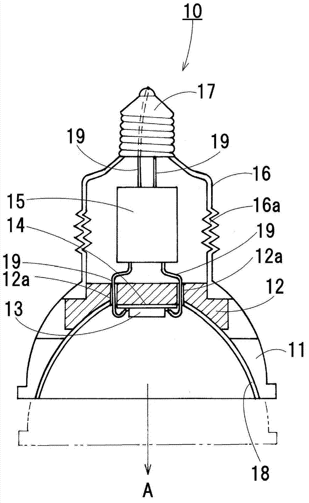
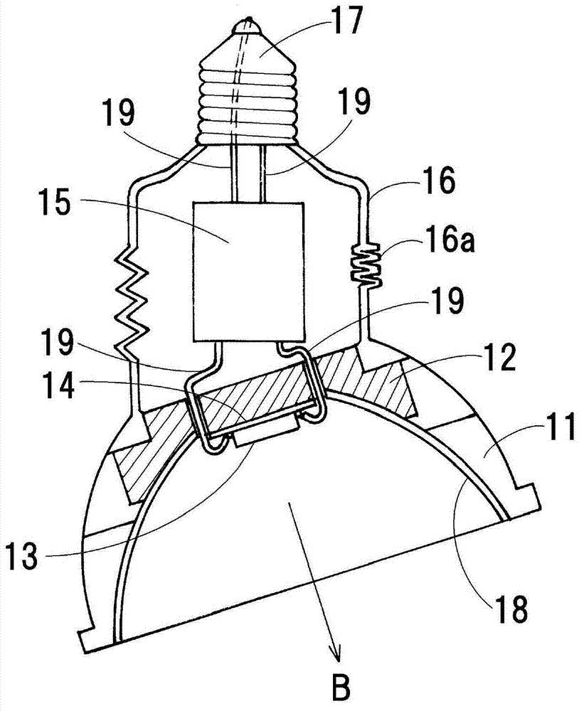
[0098] Below, the present invention will be described based on the accompanying drawings. figure 1 and figure 2 An LED lamp 10 of an embodiment of the present invention is shown in FIG. The LED lamp 10 has: a resin cover body 11; a radiator 12, which is made of metal materials such as aluminum with excellent thermal conductivity and heat dissipation; a module circuit board 14, which is equipped with an LED chip 13; a lighting circuit 15, which Power supply to LED 13 pieces; barrel member 16; lamp cap 17, which has a shape and size conforming to international standards.
[0099] The radiator 12 has a substantially flat dish shape, and the module circuit board 14 is fixed to the central portion of the inner end surface. A cup-shaped resin cover 11 is attached to the outer peripheral portion of the radiator 12 . A mirror surface 18 having a parabolic shape is formed on the inner peripheral surface of the resin cover 11 .
[0100] One end of the cylindrical member 16 is attac...
no. 2 example
[0109] image 3 and Figure 4 An LED lamp 20 of a second embodiment of the present invention is shown. This LED lamp 20 has a barrel member 21 made of plastic, and one end of the barrel member 21 is mounted on the outer peripheral portion of the radiator 12, and a lamp cap 17 is mounted on the other end. In addition, a lighting circuit 15 is provided inside the cylindrical member 21 .
[0110] The tube member 21 is composed of a large-diameter tube part 21a, a small-diameter tube part 21b, and a tapered annular surface 21c connecting the large-diameter tube part 21a and the small-diameter tube part 21b. The base 17 is connected to the small-diameter cylindrical portion 21b.
[0111] as in Figure 5 As shown in the enlarged illustration, the large-diameter cylindrical portion 21a and the small-diameter cylindrical portion 21b have substantially the same thickness T1, and the thickness T2 of the tapered annular surface 21c is formed to be thinner than the thickness T1. In a...
no. 3 example
[0120] Figure 8 An LED lamp of a third embodiment is shown. This LED lamp 30 has a barrel portion 31 made of plastic. The barrel portion 31 is composed of a large-diameter barrel portion 31a, a small-diameter barrel portion 31b, and a tapered annular surface 31c connecting the large-diameter barrel portion 31a and the small-diameter barrel portion 31b. 31c has substantially the same thickness, and a plurality of circular through-holes 31d are formed in the tapered annular surface 31c. In particular, through-holes 31e are formed at equal intervals along the entire circumference of the large-diameter cylindrical portion 31a at the connecting portion between the large-diameter cylindrical portion 31a and the tapered annular surface 31c. In addition, through-holes 31f are formed at equal intervals along the entire circumference of the small-diameter cylindrical portion 31b at a portion close to the connecting portion between the small-diameter cylindrical portion 31b and the ta...
PUM
 Abstract
Description
Claims
Application Information
 - R&D Engineer
- R&D Manager
- IP Professional
- Industry Leading Data Capabilities
- Powerful AI technology
- Patent DNA Extraction
Browse by: Latest US Patents, China's latest patents, Technical Efficacy Thesaurus, Application Domain, Technology Topic, Popular Technical Reports.
© 2024 PatSnap. All rights reserved.Legal|Privacy policy|Modern Slavery Act Transparency Statement|Sitemap|About US| Contact US: help@patsnap.com