Floating bulb type cut-off valve

A technology of floating ball head and stop valve, which is applied in the direction of lifting valve, valve device, engine components, etc., can solve the problems of valve leakage, wear of stop valve sealing surface, etc., and achieve the effect of improving sealing reliability and avoiding wear

Inactive Publication Date: 2013-03-13
SHANGHAI AEROSPACE SYST ENG INST
View PDF4 Cites 3 Cited by
  • Summary
  • Abstract
  • Description
  • Claims
  • Application Information

AI Technical Summary

Problems solved by technology

[0005] In order to overcome the defects of the prior art, the present invention discloses a floating ball stop valve, which solves the defects of the sealing surface wear of the existing stop valve and the difficulty of aligning the ball head and the shell, resulting in valve leakage. , improve the sealing reliability of the stop valve

Method used


Image

  • Floating bulb type cut-off valve

Examples


Embodiment

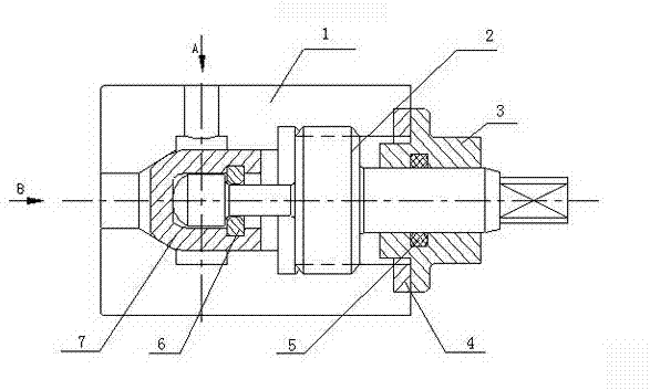
[0022] The sealing cap 7 can be arranged in the accommodating space of the housing 1, and the screw rod 2 is movably connected with the sealing cap 7. The sealing cap 7 can be provided with a groove. The screw head of the screw 2 can just be accommodated in the groove, and the head of the screw 2 is movably connected with the screw through a baffle 6 . The screw rod 2 transmits the axial force to the sealing cap; the baffle plate can be clamped on the connecting arm arranged in the accommodation groove of the sealing cap, such as figure 1 , the screw head can be a ball head structure; the sealing cap can be a floating type.

[0023] like figure 1 , the floating ball stop valve can also include a threaded sleeve 3, which is connected to the screw 2, and the threaded sleeve 3 is arranged outside the housing 1; and the globe valve also includes a sealing ring 4, so The sealing ring is arranged on the edge part of the housing; the connection between the screw sleeve and the scr...


PUM


Abstract

The invention discloses a floating bulb type cut-off valve, which comprises a shell, a screw rod and a sealing cap, wherein an accommodating space is formed in the shell; the screw rod and the sealing cap can be arranged in the accommodating space; the sealing cap can be provided with a groove; the screw rod head part of the screw rod can be just accommodated in the groove; the screw rod is movably connected with the sealing cap; and the screw rod is used for transmitting axial force to the sealing cap. Due to the adoption of the cut-off valve, the defects of valve leakage caused by wear of the sealing surface of the conventional cut-off valve and difficulty in aligning a bulb with the shell is are overcome, and the sealing reliability of the cut-off valve is enhanced.

Description

technical field [0001] The invention relates to the field of stop valves, in particular to a floating ball head type stop valve. [0002] Background technique [0003] The shut-off valve is a stand-alone unit used in the pressurized conveying system of the launch vehicle. Its function is to test the pressure of the storage tank on the ground. When the pressure measurement is required, the shut-off valve is opened manually. After the pressure measurement is completed, the shut-off valve is manually closed and sealed. It can be used many times. In the stop valve used in the existing pressurized conveying system, the screw and the sealing cap adopt an integrated structure, so that the sealing surface of the screw and the sealing surface of the shell will rotate relative to each other during the opening and closing process, which will easily lead to wear of the sealing surface, which is not conducive to sealing. ; On the other hand, the integrated structure requires high coaxia...

Claims


Application Information

Patent Timeline
Patent Type & Authority Applications(China)
IPC IPC(8): F16K1/48F16K1/36
Inventor 滕浩李军刘红宝赵永立张亮
Owner SHANGHAI AEROSPACE SYST ENG INST
Why Eureka
Try Eureka