Eureka AIR delivers breakthrough ideas for toughest innovation challenges, trusted by R&D personnel around the world.

Chlorine stop valve

A shut-off valve, chlorine technology, applied in the direction of lift valve, valve details, valve device, etc., can solve the problems of reducing the service life of bellows, accumulation of dirt, and reduced safety of the valve cover, so as to reduce the accumulation of dirt, facilitate maintenance and The effect of replacing and improving the service life

Inactive Publication Date: 2013-03-13
JIANGSU DINGSHENG VALVE
View PDF6 Cites 5 Cited by
  • Summary
  • Abstract
  • Description
  • Claims
  • Application Information

AI Technical Summary

Problems solved by technology

The defects caused by this structure of the handwheel assembly are: the valve stem thread is exposed, and the lubricating oil of the valve stem thread is easy to stick to dust, causing the thread to be stuck; It is easy to cause deformation of the valve stem
The defects caused by the sealing packing and the pressure plate structure are: when the pressure plate is tightened, if the force on both ends is uneven, it is easy to cause the inner hole of the pressure plate to scratch the valve stem.
Due to the segmented welding method, the overall safety of the bonnet is reduced; the bonnet with a long neck design completely covers the bellows in the bonnet, and dirt will accumulate on the outer surface of the bellows after long-term use, which is inconvenient to clean dirt and reduce The service life of the bellows
The connection between the disc and the valve stem adopts a non-detachable structure or a detachable but non-detachable disc nut. If the disc or disc nut is damaged, the valve will not be able to be used and repaired and will be scrapped.

Method used


Image

  • Chlorine stop valve
  • Chlorine stop valve
  • Chlorine stop valve

Examples


Embodiment Construction

[0014] The specific content of the present invention will be described in detail below in conjunction with the accompanying drawings and specific embodiments.

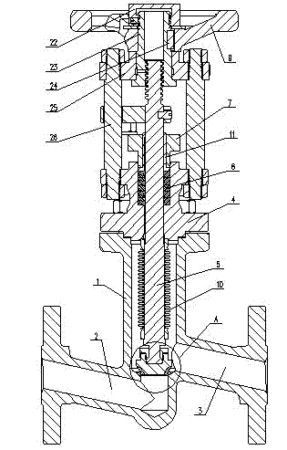
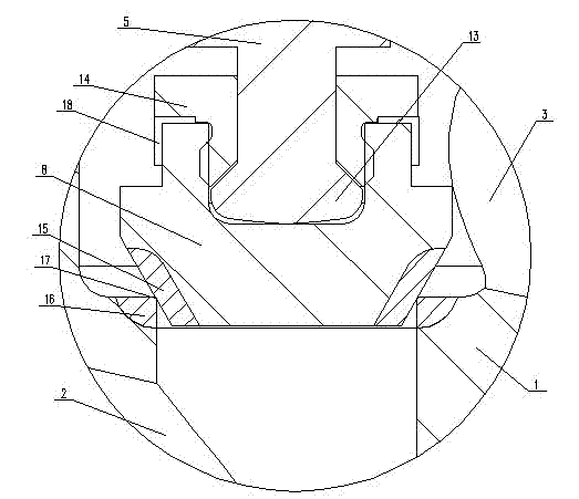
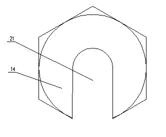
[0015] Such as figure 1 , figure 2 , image 3 , Figure 4 As shown, the chlorine shut-off valve includes: a valve body 1, an inlet channel 2 and an outlet channel 3 at the lower end of the valve body 1; a valve cover 4 is arranged at the upper end of the valve body 1; The upper end of 5 is connected to the hand wheel assembly, and the lower end is connected to the disc assembly; a sealing packing 6 and a pressure plate 7 are arranged between the valve stem 5 and the valve cover 4; a bellows 10 is provided at the lower section of the valve stem 5, and one end of the bellows 10 is welded On the bonnet 4, the other end is welded on the valve stem 5; the disc 8 cooperates with the valve port sealing surface 17 between the inlet channel 2 and the outlet channel 3; Body 1 is designed with a long neck. The total height ...


PUM


Abstract

The invention provides a chlorine stop valve which relates to a valve. The chlorine stop valve comprises a valve body, and an inlet passage and an outlet passage at the lower end of the valve body, wherein a valve cover is arranged at the upper end of the valve body; a valve rod penetrates through the valve cover; the upper end of the valve rod is connected with a hand wheel assembly; the lower end of the valve rod is connected with a valve clack assembly; a gland packing and a pressing plate are arranged between the valve rod and the valve cover; a corrugated pipe is arranged at the lower section of the valve rod; one end of the corrugated pipe is welded on the valve cover and the other end thereof is welded on the valve rod; and a valve clack is matched with a valve port sealing surface between the inlet passage and the outlet passage. The chlorine stop valve is characterized in that the valve cover is short; the valve body adopts a long neck design; the total height of the short valve cover is less than the maximum outside diameter of the valve cover; and the vertical distance from an upper plane of a middle flange of the long neck valve body to the highest point of a side flange of the valve body exceeds 1.5 times the diameter of a flow passage. The chlorine stop valve has the advantages that the chlorine stop valve is self-cleaning, long in service life, higher in overall safety, and convenient to dismount, maintain and replace.

Description

technical field [0001] The invention relates to a valve, in particular to a chlorine stop valve. Background technique [0002] Chlorine gas stop valve is a commonly used valve in the chemical industry to control and regulate strong corrosive flow media such as chlorine gas. The structure of the existing chlorine stop valve includes: a valve body, an inlet channel and an outlet channel at the lower end of the valve body; a valve cover is arranged at the upper end of the valve body; Connect the valve disc assembly; a sealing packing and a pressure plate are arranged between the valve stem and the valve cover; a bellows is provided at the lower part of the valve stem, one end of the bellows is welded on the valve cover, and the other end is welded on the valve stem; the valve disc and the The sealing surface of the valve port fits between the inlet channel and the outlet channel. As mentioned above, the handwheel assembly includes a handwheel and a valve stem nut, the valve s...

Claims


Application Information

Patent Timeline
IPC IPC(8): F16K1/02F16K1/36F16K1/48F16K27/12F16K41/10
Inventor 龚正林刘长军马丁.格林哈尔什顾云飞康邦华
Owner JIANGSU DINGSHENG VALVE
Why Eureka
Eureka Blog
Learn More