
Pulse laser drilling device and drilling method thereof

A pulse laser and short pulse technology, applied in laser welding equipment, welding equipment, metal processing equipment, etc., can solve the problems of affecting the processing quality of the workpiece, the material of the hole wall is greatly affected by heat, and the hole shape accuracy is not easy to control, etc., to achieve shape accuracy Guarantee, reduce the scope, eliminate the effect of too much slag spray

Active Publication Date: 2015-05-20
JIANGSU JINFANGYUAN CNC MACHINE CO LTD
View PDF9 Cites 1 Cited by
  • Summary
  • Abstract
  • Description
  • Claims
  • Application Information

AI Technical Summary

Problems solved by technology

Its shortcoming is that: due to the continuous melting of materials for hole processing by continuous laser beams, the workpiece melt continuously transfers heat to the base material, and the diameter of the molten pool on the surface of the workpiece is much larger than the diameter of the spot, while the diameter of the molten pool at the bottom of the molten pool and the diameter of the spot Close, so the formed hole is often tapered, and the shape accuracy of the hole is not easy to control; at the same time, because the workpiece is continuously heated, the material of the hole wall is greatly affected by the heat; Accumulation, forming bulges after cooling, affects the processing quality of the workpiece, so follow-up processing is often required to ensure the quality of the workpiece

Method used


Image

  • Pulse laser drilling device and drilling method thereof

Examples


Embodiment Construction

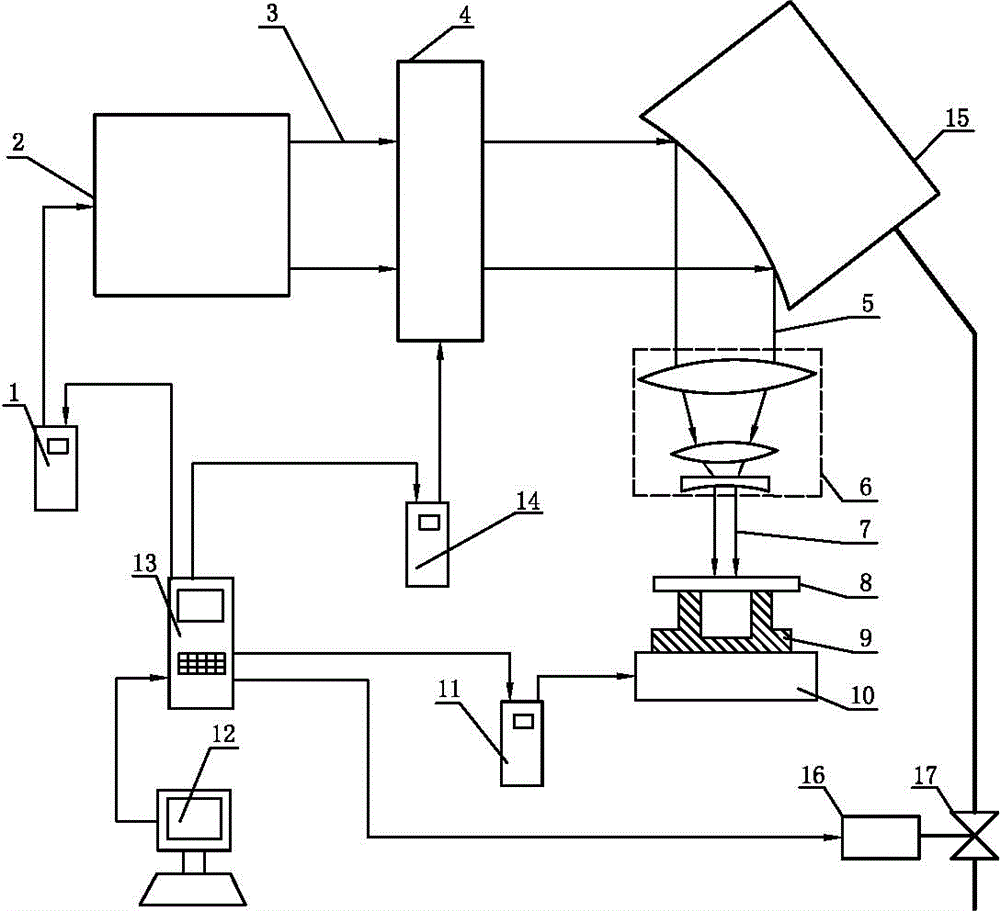
[0015] Such as figure 1 A pulse laser perforation device and perforation method thereof are shown, the device includes a laser generator, an ultra-pulse converter, a pneumatic zoom mirror, a converging lens group and a fixture are sequentially arranged on the optical path of the laser generator, and the laser generator The signal input end is connected to the signal output end of the numerical control box through the laser generator control device, the air pressure zoom mirror is controlled by the air pressure valve control device, the signal input end of the air pressure valve control device is connected to the signal output end of the control box, and the ultra-pulse converter The signal input end of the digital control box is connected to the signal output end of the numerical control box through the super pulse converter control device. The fixture is fixedly installed on the numerical control workbench. The CNC box is connected with the computer;

[0016] The method incl...


PUM

PropertyMeasurementUnit
frequencyaaaaaaaaaa

Abstract

The invention discloses a pulse laser drilling device in the field of laser drilling devices and a drilling method thereof. The device comprises a laser generator, wherein an ultra pulse convertor, a plus lens group and a clamp are sequentially arranged on the light path of the laser generator; the signal input terminal of the laser generator is connected with the signal output terminal of a numerical control box through a laser generator control device; the signal input terminal of the ultra pulse convertor is connected with the signal output terminal of the numerical control box through an ultra pulse convertor control device; the numerical control box is connected with a computer; and the drilling method comprises the steps that a plurality of short pulse laser beams, with power density values being steadily increased, are focalized to be a laser focal point through the plus lens group, and the laser focal point irradiates the surface of a workpiece, so as to perform drilling. The pulse laser drilling device and the drilling method thereof improve the shape precision during hole machining, guarantee the machining quality of holes, and can be applied to laser drilling.

Description

technical field [0001] The invention relates to a perforating device, in particular to a laser perforating device. Background technique [0002] Conventional laser perforation technology uses a continuous laser beam to ablate the workpiece to melt the workpiece to form a process hole. Its shortcoming is that: due to the continuous melting of materials for hole processing by continuous laser beams, the workpiece melt continuously transfers heat to the base material, and the diameter of the molten pool on the surface of the workpiece is much larger than the diameter of the spot, while the diameter of the molten pool at the bottom of the molten pool and the diameter of the spot Close, so the formed hole is often tapered, and the shape accuracy of the hole is not easy to control; at the same time, because the workpiece is continuously heated, the material of the hole wall is greatly affected by the heat; Accumulation, forming bulges after cooling, affects the processing quality...

Claims


Application Information

Patent Timeline
Patent Type & Authority Patents(China)
IPC IPC(8): B23K26/382B23K26/0622B23K26/04
Inventor 陈树明夏建斌张永康顾永玉戴峰泽
Owner JIANGSU JINFANGYUAN CNC MACHINE CO LTD
Learn More