rectifier circuit device
A technology of rectifier circuit and AC power supply, applied in output power conversion devices, electrical components, high-efficiency power electronic conversion and other directions, can solve problems such as circuit loss, and achieve the effect of less device loss and less high-order harmonic current.
- Summary
- Abstract
- Description
- Claims
- Application Information
AI Technical Summary
Problems solved by technology
Method used
Image

Examples
Embodiment approach 1
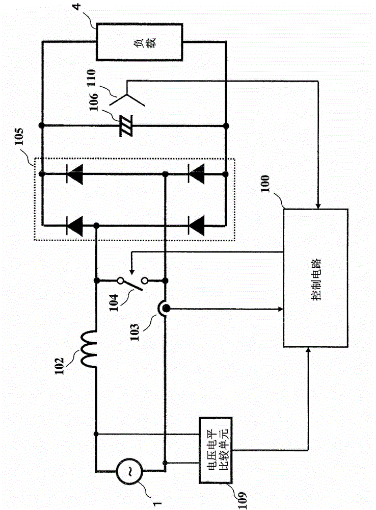
[0040] figure 1 It is a circuit block diagram showing the overall configuration of the rectifier circuit device in Embodiment 1 of the present invention.
[0041] exist figure 1 In this configuration, a circuit that short-circuits the AC power source 1 between the reactor 102 and the semiconductor switch 104 in the conduction state is formed. The current detection unit 103 is provided so as to be able to detect the current of the circuit, and the detection result is input to the control circuit 100 . If the semiconductor switch 104 is turned on to short-circuit the AC power supply 1, the current of the reactor 102 gradually increases, and if the semiconductor switch 104 is turned off, the current flowing through the reactor 102 is rectified in the diode bridge 105 and flows into the smoothing capacitor 106 and In the load 4, the load 4 is driven. The DC voltage applied to the load 4 is detected by the DC voltage detection unit 110 and input into the control circuit 100 . ...
Embodiment approach 2
[0059] Next, a rectifier circuit device according to Embodiment 2 of the present invention will be described. The rectifier circuit device of Embodiment 2 has substantially the same configuration as the rectifier circuit device of Embodiment 1 described above, but the drive control in the rectifier circuit device is different.
[0060] Figure 5 This is a waveform diagram showing the operating principle of a control method that can further reduce losses by making the target current waveform into a waveform other than a sine wave. Especially when the load is light, even if the waveform distortion increases, the harmonic current itself is small, so the loss can be further reduced. exist Figure 5 The waveforms in the middle and upper sections represent the relative relationship between the AC voltage and the DC voltage, the waveforms in the middle section are the target current waveforms, and the waveforms in the lower section are the actual current waveforms. exist Figure ...
Embodiment approach 3
[0069] Next, a rectifier circuit device in Embodiment 3 of the present invention will be described.
[0070] Figure 8 It is a circuit diagram showing a basic circuit configuration of a rectifier circuit device in Embodiment 3 of the present invention. Figure 8 The AC power source 1 of the rectifier circuit device according to Embodiment 3 shown is connected to a bridge circuit composed of semiconductor switches 604a, 604b and diodes 605a, 605b, 605c, and 605d via a reactor 602, and rectified in the bridge circuit Current is supplied to the smoothing capacitor 106 and the load 4 to drive the load 4 . The control method in the rectifier circuit device of Embodiment 3 and figure 1 It is the same as Embodiment 1 shown, and is realized by simultaneously driving the two semiconductor switches 604a and 604b.
PUM
 Abstract
Description
Claims
Application Information
 - R&D
- Intellectual Property
- Life Sciences
- Materials
- Tech Scout
- Unparalleled Data Quality
- Higher Quality Content
- 60% Fewer Hallucinations
Browse by: Latest US Patents, China's latest patents, Technical Efficacy Thesaurus, Application Domain, Technology Topic, Popular Technical Reports.
© 2025 PatSnap. All rights reserved.Legal|Privacy policy|Modern Slavery Act Transparency Statement|Sitemap|About US| Contact US: help@patsnap.com