Door handle assembly of a motor vehicle

A technology for car door handles and facilities, which is applied to the spherical handle of the wing leaf, the vehicle lock, and the handle of the wing leaf. Effect

Active Publication Date: 2013-03-06
HUF HULSBECK & FURST GMBH & CO KG
View PDF6 Cites 4 Cited by
  • Summary
  • Abstract
  • Description
  • Claims
  • Application Information

AI Technical Summary

Problems solved by technology

[0004] A disadvantage of the state of the art is that the construction of the door handle installation comprises expensive and numerous components

Method used


Image

  • Door handle assembly of a motor vehicle
  • Door handle assembly of a motor vehicle
  • Door handle assembly of a motor vehicle

Examples


Embodiment Construction

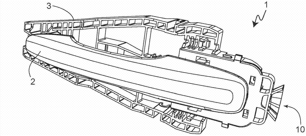
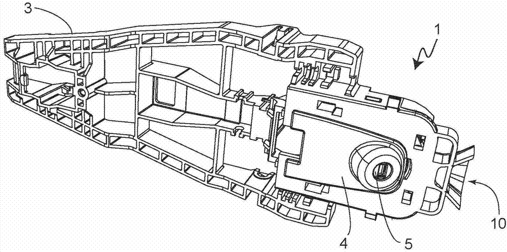
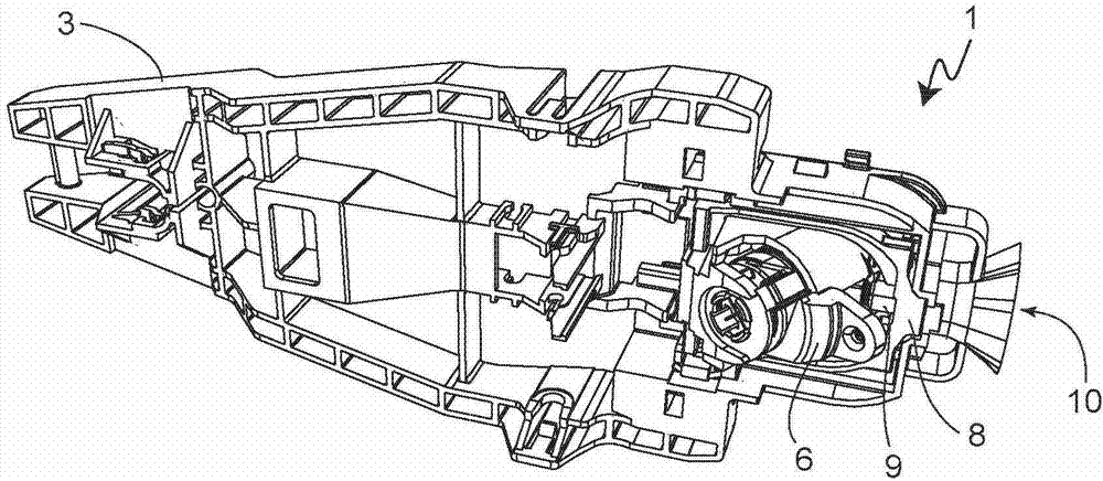
[0031] exist Figure 1 to Figure 4 A door handle arrangement 1 according to the invention of a vehicle is shown in various views, wherein figure 1 , figure 2 as well as Figure 4 shows a stereoscopic front view, conversely, in image 3 What can be seen in is the perspective rear view. The door handle arrangement 1 is fastened to a vehicle wall (not shown in the figures) and comprises a support frame 3 and a handle 2 which is rotatably mounted on the support frame 3 and which can be pivoted between a rest position and an actuating position. In addition to housing the handle 2, the support frame 3 also serves to accommodate the door handle assembly. The carrier 3 is mounted on the vehicle side and in particular on the inside behind a door panel, wherein an opening in the door panel makes it possible, for example, to attach the handle 2 from the outside. At least in its rest position, the handle 2 covers a lock cylinder housing 4 in which a lock cylinder 5 is arranged and a...


PUM


Abstract

The door handle assembly (1) comprises a lock cylinder (5), and a bearing bracket (3) for receiving the door handle components, which is coupled with a lock cylinder housing (4). The bearing bracket has a receptacle for accommodating the housing. The outer contour of housing is coordinated on the inner contour of receptacle so that at least one region of contact between the housing and receptacle forms a slide-gate which enables movement of housing during insertion into receptacle along a spatial direction which is oblique to other spatial direction.

Description

technical field [0001] The invention relates to a door handle installation for a vehicle, having a lock cylinder arranged and housed in a lock cylinder housing, and a support frame capable of being assembled on the side of the vehicle for receiving a vehicle door handle assembly, wherein the lock cylinder housing can be connected with The support frame is connected so that the lock core can be fixedly arranged on the support frame. Background technique [0002] Such door handle facilities are used, for example, when the vehicle is basically designed with electronic access functions (Keyless-Entry). The application of a mechanical locking function, which is usual in vehicles, is then no longer necessary. Due to brief or continuous disturbances or eg depletion of the device, the battery is required for the electronic access function, but a mechanical emergency or auxiliary locking device is provided on at least one door handle arrangement of the vehicle. A lock cylinder is p...

Claims


Application Information

Patent Timeline
IPC IPC(8): E05B9/08E05B17/18E05B7/00
CPCE05B85/16E05B7/00E05B1/00E05B85/06E05B9/08E05B17/18E05B79/02E05B17/14
Inventor 马蒂亚斯・勒夫
Owner HUF HULSBECK & FURST GMBH & CO KG
Why Eureka
Try Eureka