Method and device for producing a translucent multilayer composite building element with integrated facade panels

A multi-layer composite and manufacturing method technology, which is applied in the direction of building components, buildings, building structures, etc., can solve problems such as difficulty in alignment of light guide rods, difficulty in connecting external wall panels and surface layers, etc.

Inactive Publication Date: 2017-03-01
迪特尔·克里斯但丁 +2
View PDF4 Cites 0 Cited by
  • Summary
  • Abstract
  • Description
  • Claims
  • Application Information

AI Technical Summary

Problems solved by technology

But this has the disadvantage that it is very difficult to align the drilled holes in the façade with the front of the light guide rods fixed on the surface layer
In addition, it is also very difficult to connect the exterior wall panels with the surface layer through binding and other means
[0010] In addition, since the thickness of the outer wall panel is, for example, between 2 and 5 mm, the drilled hole of the outer wall panel added in front is not filled into the light guide rod but only used as the space before the front side of the light guide rod. drilling is disadvantageous
First, this leads to undesired light loss as the light needs to travel further through the empty borehole and be scattered within the empty borehole
Secondly, the accumulation of dust and debris in the hollow boreholes can also cause problems. After a long period of use, such multi-layer facade elements can completely cover the illuminated front side of the glow stick due to the accumulation of dust and debris.

Method used


Image

  • Method and device for producing a translucent multilayer composite building element with integrated facade panels
  • Method and device for producing a translucent multilayer composite building element with integrated facade panels
  • Method and device for producing a translucent multilayer composite building element with integrated facade panels

Examples


Embodiment Construction

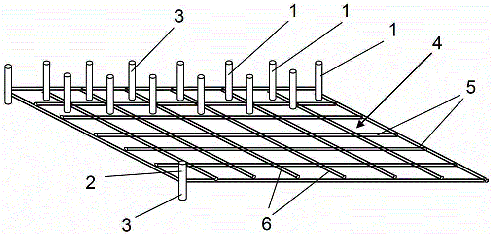
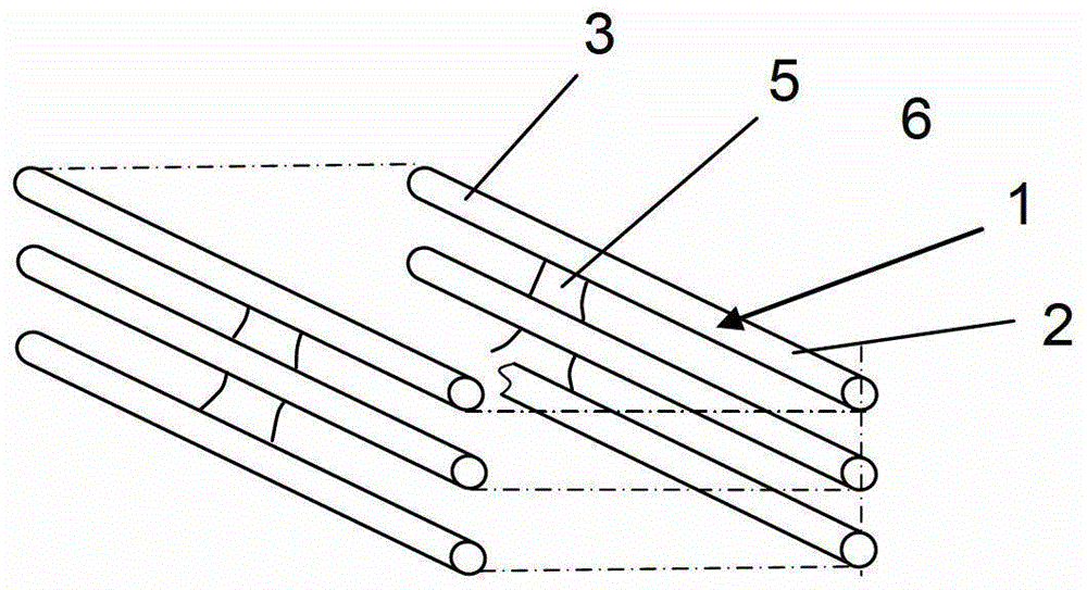
[0056] like figure 1 , 2 As shown, the light guide rods 1 can have any shape, composition and cross section, and the distance between each light guide rod is maintained by an additional fixing element.

[0057] In the illustrated embodiment, each light guiding bar is formed of a light guiding plastic material, such as polycarbonate or the like. Each light guide rod 1 has an upper end 2 and a lower end 3, and the upper end and the lower end can have any contour.

[0058] according to figure 1 , 2 The embodiment of the present invention shows that the light guide rod 1 is injected at the intersection of a grid mat 4 comprising interconnected longitudinal beams 5 and cross beams 6.

[0059] The longitudinal beams 5 and crossbeams 6 are also formed of light-guiding plastic materials, which benefit from the good uniform light distribution across the surface of the grid pad 4 generated by the light-guiding beams and stringers, and are arranged on the grid pad 4 The light distri...


PUM


Abstract

The method involves fixing a light guiding element (1) in a thermally insulated layer to form an insulating body. The insulating body fixed light guiding element is inserted into shuttering plates (18, 19) formed by a mold space (17) of a mold form (20). The mold space is filled with a curable potting compound (26) to form a supporting layer. The shuttering plates are formed of facade panels (21, 22) with holes (23) or recesses, where the shuttering plates are used as permanent shuttering elements. Front sides of the light guiding element are partially received in the facade panels. The facade panels are made of light metal alloy, plastic or wood. The light guiding element is designed as rigid light-conducting rod or a light guiding disk. An independent claim is also included for a multilayer composite construction element for a facade of a building.

Description

technical field [0001] The invention relates to a method and a device for producing a translucent multilayer composite building element with integrated facade panels, and to a translucent multilayer composite building element with integrated facade panels produced by the method. Background technique [0002] EP 1970179A 2 discloses a method and an apparatus for the production of translucent multilayer composite building elements. This document is incorporated herein by reference in its entirety, such that this application includes the entire content of this document. [0003] In the aforementioned publication, translucent multi-layer composite building elements are produced by first inserting rigid light-guiding rods into drilled holes in an insulating body so that the ends of the light-guiding rods are guided from opposite Both surfaces protrude. [0004] The base body thus produced is then placed in a formwork, the formwork space of which is provided with a curable casti...

Claims


Application Information

Patent Timeline
Patent Type & Authority Patents(China)
IPC IPC(8): E04C2/54
CPCB28B19/0015B28B19/003B28B23/0037B29C39/10E04C2/54Y10T29/4998Y10T428/24322Y10T428/24612
Inventor 迪特尔·克里斯但丁约瑟夫·克里斯但丁罗伯特·霍夫尔亚历山大·海德尔奥利弗·费歇尔
Owner 迪特尔·克里斯但丁
Why Eureka
Try Eureka