
Textile machine with a large number of work positions

A technology of textile machinery and workstations, applied in the direction of continuous winding spinning machine, spinning machine, textile and papermaking, etc., can solve the problems of high cost and complicated manufacturing

Inactive Publication Date: 2013-03-06
SAURER TECH GMBH & CO KG
View PDF10 Cites 11 Cited by
  • Summary
  • Abstract
  • Description
  • Claims
  • Application Information

AI Technical Summary

Problems solved by technology

[0013] However, a significant disadvantage of this magnetic drive, which is advantageous in itself, is that it is relatively complex to manufacture, which makes such a magnetic drive rather costly, especially compared to the aforementioned endless traction belts

Method used


Image

  • Textile machine with a large number of work positions
  • Textile machine with a large number of work positions
  • Textile machine with a large number of work positions

Examples


Embodiment Construction

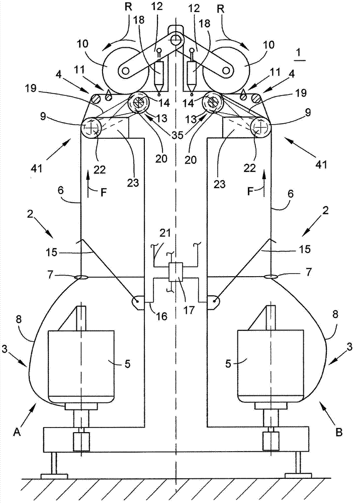
[0043] figure 1 A multi-station textile machine is shown schematically in a side view, in this example a double twister or a flyer type multi-strand rope twister 1 . As is known, such a textile machine has several stations 2 arranged side by side on both sides of the longitudinal axis of the machine. The station 2 of such a double twister or flyer 1 is especially equipped with a double twist device 3 and a winding device 4 . exist figure 1 In the embodiment shown, the yarn 6 drawn off by the double twist spindle 5 is passed to the winding device 4 via a yarn guide 7 which, during the twisting operation, delimits the yarn present in the region of the twisting device 3 . The height of the balloon 8 at which the yarn 6 is wound into a cross-wound bobbin 10 .

[0044] As is customary, the winding device 4 has a creel 12 for rotatably holding the cross-wound bobbins 10 , wherein the creel 12 can be lifted as required by means of a cylinder 18 . Furthermore, the winding device 4...


PUM


Abstract

The textile machine (1) has drive equipment (20) arranged on a drive shaft (35) that is extended over multiple work stations (2) of the textile machine. Two coaxial deflection- and guide grooves arranged with the drive shaft, where two strands of the drive shaft drawn around an endless tensile unit (19) are inserted in the grooves. The resulting loops of the endless tensile unit in the region of a corresponding cantilevered yarn processing unit (41) are guided in the deflection- and guide grooves of the output units (22). The output units are connected to the respective yarn processing units.

Description

technical field [0001] The present invention relates to a textile machine with a plurality of stations according to the preamble of claim 1 . Background technique [0002] In textile machine construction, various embodiments of textile machines with a plurality of identical stations have been known for a long time and are well documented in a large number of patent documents. [0003] Such textile machines, which are often also referred to as multi-station textile machines, are, for example, rotor spinning machines, open-end spinning machines, crimping machines, spindle roving machines, ring spinning machines, double twisters or spindle multi-twist machines. rope machine, etc. Such multi-station textile machines generally have at least one generally continuous drive shaft extending in the longitudinal direction of the textile machine, to which a plurality of, for example floatingly mounted, yarn handling mechanisms are connected. [0004] A double twister or a flyer type m...

Claims


Application Information

Patent Timeline
Patent Type & Authority Applications(China)
IPC IPC(8): D01H1/20D01H1/24D01H13/00D01H13/30D01H4/42
CPCB65H71/00D01H13/00B65H2701/31B65H59/18D01H1/22B65H54/42B65H51/12B65H54/74B65H51/06
Inventor 乔治·海嫩于尔根·施尼茨勒J·奇施斯基
Owner SAURER TECH GMBH & CO KG
Learn More