
Closed pneumatic shell vibrating machine

A vibrating shell machine and closed technology, applied in the field of precision casting, can solve the problems of dust easily affecting the environment, unreliable clamping, large vibration and impact, etc., to achieve the effect of protecting physical and mental health, improving the operating environment and prolonging the service life

Inactive Publication Date: 2013-03-06
TAIZHOU XINYU PRECISION MFG CO LTD
View PDF13 Cites 5 Cited by
  • Summary
  • Abstract
  • Description
  • Claims
  • Application Information

AI Technical Summary

Problems solved by technology

When using this device to vibrate the shell, the pouring riser of the poured formwork is upward, and the pouring riser is hung on the formwork hanging opening of the supporting plate, and then the wind pick is vibrated against the pouring riser to make the mold shell In the process of vibrating the shell, the precision casting is suspended in the air without contact with the worktable, so the precision casting will not be damaged by the extrusion of the pick and the worktable, but this device also has shortcomings. First, this device is not closed , a large amount of dust generated when vibrating the shell is likely to affect the environment, and it will also have a negative impact on the physical and mental health of the operators; second, the vibration impact when vibrating the shell is relatively large, and the mold shell is in a suspended state, and long-term vibration impact will cause clamping The failure of the mechanism will easily cause unreliable clamping, and in severe cases, the mold shell will fall off during the vibration process

Method used


Image

  • Closed pneumatic shell vibrating machine
  • Closed pneumatic shell vibrating machine
  • Closed pneumatic shell vibrating machine

Examples


Embodiment Construction

[0014] The present invention will be further described below according to the accompanying drawings and in conjunction with the embodiments.

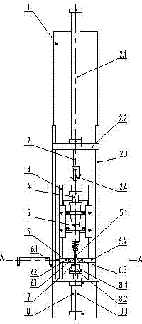
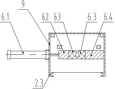
[0015] The enclosed pneumatic shell vibrating machine shown in the accompanying drawings includes a pneumatic pick 5, a frame 3, a cylinder 4, a chassis 9, supporting feet 10, a movable door 1, a pneumatic opening and closing structure 2, a clamping mechanism 6 and an auxiliary supporting mechanism 8. The air pick 5 is fixedly connected to the frame 3, the upper end of the air pick 5 is connected to the cylinder 4, the air pick 5, the frame 3, and the cylinder 4 are arranged in the chassis 9; the chassis 9 is provided with supporting feet 10; the chassis 9 is Only the unclosed box-shaped member at the front is provided with a movable door 1 and a pneumatic opening and closing structure 2 on its unclosed front. The pneumatic opening and closing structure 2 includes a movable door guide rail 2.3, a cylinder support plate 2.2, a movable...


PUM


Abstract

The invention discloses a closed pneumatic shell vibrating machine which comprises a pneumatic pick, a frame, a cylinder, a case, support legs, a moving door, a pneumatic open-close structure, a clamping mechanism and an auxiliary support mechanism. The pneumatic pick, the frame and the cylinder are disposed in the case. The open front side of the case is provided with the moving door and the pneumatic open-close structure. The clamping mechanism is horizontally disposed below the pneumatic pick. Opposing sides of a moving clamping block and a fixed clamping block are provided with opposing semi-conical openings. The auxiliary support mechanism is vertically disposed below the clamping mechanism and right below the pneumatic pick. When shell vibrating occurs in the closed environment, mass dust produced by shell vibrating is prevented from spreading out, and accordingly operating environment is evidently improved. During shell vibrating, a mould shell is tightly clamped and suspended, so that precision castings are protected from damage caused by rigid extrusion. A flexible support block assists in supporting the mould shell, so that stress condition of the mould shell and the clamping mechanism can be evidently improved during shell vibrating, clamping is reliable and the service life of the clamping mechanism is effectively prolonged.

Description

technical field [0001] The invention belongs to the field of precision casting, and in particular relates to a pneumatic shell vibration device for shell removal after precision casting. Background technique [0002] At present, the cleaning of the mold shell in the precision casting process generally adopts a vertical pneumatic shell vibrating machine. The commercially available pneumatic shell vibrating machine includes a frame, a cylinder, a pick, and a workbench. Fix the air pick on the top, and the upper end of the air pick is connected with the cylinder. When using this kind of pneumatic shell vibration machine to vibrate the shell, place the poured formwork vertically on the workbench, and vibrate the air pick head against the pouring riser, so that The shell falls off, which can achieve the purpose of shelling, but the precision casting is easily damaged by the extrusion of the pick and the workbench. Chinese Patent Publication No. CN201415258 discloses a pneumatic ...

Claims


Application Information

Patent Timeline
IPC IPC(8): B22C19/06
Inventor 荆剑王小东刘玉军
Owner TAIZHOU XINYU PRECISION MFG CO LTD
Learn More