Controllable silicon dimming circuit with nondestructive leakage circuit and method thereof
A bleeder circuit and silicon dimming technology, applied in the field of power electronics, can solve the problems of complex bleeder circuit structure and high energy consumption, and achieve the effect of improving utilization efficiency and simple circuit structure
- Summary
- Abstract
- Description
- Claims
- Application Information
AI Technical Summary
Problems solved by technology
Method used
Image

Examples
Embodiment 1
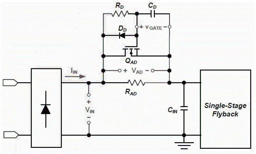
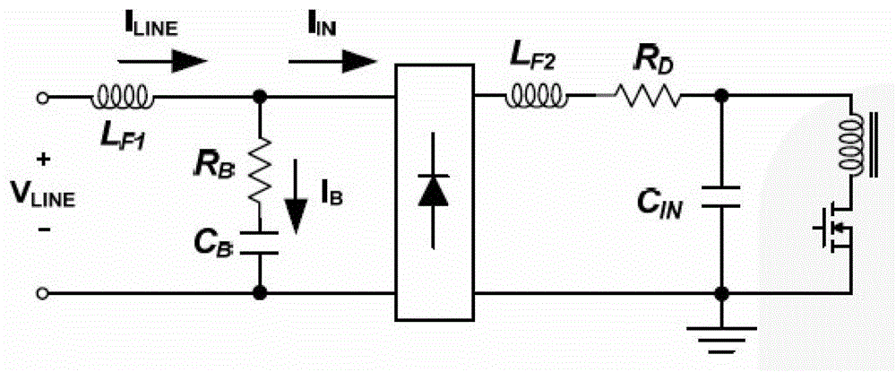
[0041] see figure 1 , is a schematic diagram of a discharge circuit commonly used in the prior art. Taking the power stage circuit as a single-stage flyback converter circuit as an example, since it is necessary to provide a charging current loop for the thyristor circuit to ensure the normal operation of the circuit , whose bleeder circuit consists of a resistor R D , capacitance C D , Diode D D and switch tube Q AD wait, from figure 1 It is not difficult to see that its circuit structure is complex, and the corresponding circuit cost is relatively high. In addition, the bleeder circuit can also be figure 2 way, a resistor R is connected in series between the bus voltage and the ground B and capacitance C B , the circuit structure is simple, but because it is connected to the bus voltage, it needs to consume electricity all the time.
[0042] In view of the above technical problems, the present invention provides a thyristor dimming circuit with a lossless discharge ...
Embodiment 2
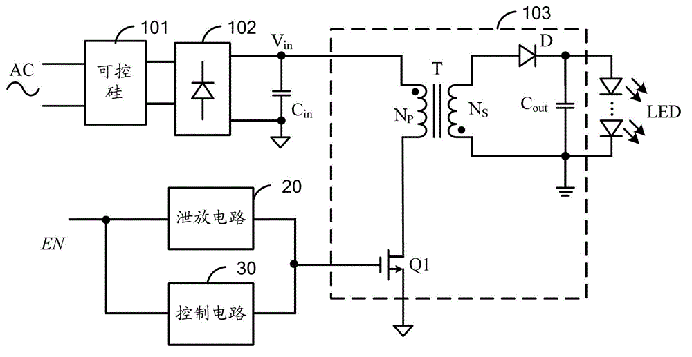
[0051] On the basis of Embodiment 1, the present invention also provides an enable signal generating circuit 40, please refer to Figure 4 , so as to output an enable signal to the control circuit 30 and the discharge circuit 20 . The dimming circuit in this embodiment still takes the flyback topology composed of the thyristor 101, the rectifier bridge 102 and the power stage circuit 103 as an example. The enabling signal generating circuit 40 includes: a comparison circuit 401 and a single pulse generating circuit 402 .
[0052] The comparison circuit 401 receives and compares the phase-missing input voltage V in and a threshold signal V th , outputting a pulse signal according to the comparison result, the single pulse generating circuit 402 receives the pulse signal, and accordingly outputs the enable signal EN which remains valid in the second time interval.
[0053] It should be noted that the comparison circuit 401 may be a comparator U1, the non-inverting input termi...
Embodiment 3
[0060] When the comparator U1 is used in the comparison circuit 401, the Figure 5 It is not difficult to find that the comparator will output a high level during the period from point M to point N. In order to shield this part of the signal, it is ensured that the enable signal EN remains valid only within the second preset time interval. The enabling signal generating circuit further includes a phase angle detection circuit 4011 and a first switch tube S1, such as Figure 6 shown, aims at the phase loss of the input voltage V in When the angle is between 90° and 180°, the comparison circuit is controlled to output a high level.
[0061] Specifically, the first switching tube S1 can be connected to the threshold signal V th and the non-inverting input terminal of the comparator U1, correspondingly, the input terminal of the phase angle detection circuit receives the input voltage V of the phase loss in , the output terminal is connected to the control terminal of the first...
PUM
 Abstract
Description
Claims
Application Information
 - R&D
- Intellectual Property
- Life Sciences
- Materials
- Tech Scout
- Unparalleled Data Quality
- Higher Quality Content
- 60% Fewer Hallucinations
Browse by: Latest US Patents, China's latest patents, Technical Efficacy Thesaurus, Application Domain, Technology Topic, Popular Technical Reports.
© 2025 PatSnap. All rights reserved.Legal|Privacy policy|Modern Slavery Act Transparency Statement|Sitemap|About US| Contact US: help@patsnap.com