Method and system of flow control based on exchanger cache allocation

A buffer allocation and flow control technology, applied in the field of data transmission, can solve the problems of increasing congestion, large end-to-end delay of short data flow, and lack of generality, so as to reduce congestion and solve large delay of short flow. Effect

Active Publication Date: 2013-02-27
TSINGHUA UNIV
View PDF4 Cites 16 Cited by
  • Summary
  • Abstract
  • Description
  • Claims
  • Application Information

AI Technical Summary

Problems solved by technology

It mainly includes three aspects: 1. The end-to-end delay of short flow is very large: due to the coexistence of long data flow and short data flow in the data center network, TCP consumes too much buffer space of the switch, causing the long data flow to fill the switch Most of the cache, short data streams are forced to wait in the queue and make the end-to-end delay very large
2. TCPincast problem: The incast problem refers to that when multiple senders send data to the same receiver in parallel in units of data blocks, a large number of packet loss in the bottleneck buffer pool causes many timeout retransmissions, resulting in a sharp drop in throughput
3. TCPoutcast problem: When multiple streams and a few streams compete for the same exit, the throughput is not fair due to continuous packet loss in a few streams
[0004] However, the existing solutions are generally only aimed at solving a certain problem, and will bring other problems
For example, although increasing the initial window of TCP proposed by Google can reduce the end-to-end delay of short flows, it increases the degree of congestion, which will deteriorate the transmission performance in the incast transmission mode, especially when the number of senders is large.
The solution to the TCP incast problem by reducing the TCP minimum retransmission time RTOmin is not universal, and when the server inside the data center communicates with the server outside the data center, it may also cause timeout retransmission

Method used


Image

  • Method and system of flow control based on exchanger cache allocation
  • Method and system of flow control based on exchanger cache allocation
  • Method and system of flow control based on exchanger cache allocation

Examples


Embodiment Construction

[0038] The specific implementation manners of the present invention will be further described in detail below in conjunction with the accompanying drawings and embodiments. The following examples are used to illustrate the present invention, but are not intended to limit the scope of the present invention.

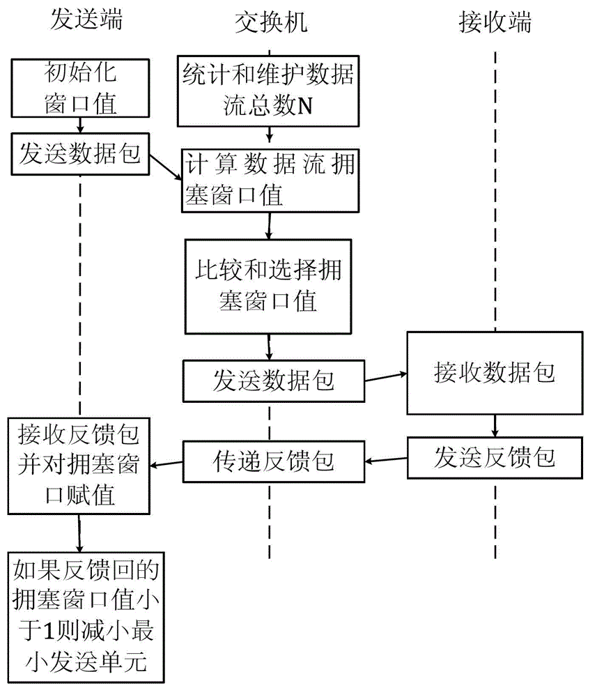
[0039] Such as figure 1 As shown, the sender initializes the field of the congestion window carried in the data packet, such as the window field of 16 bits in the TCP packet header, the initial value can be 0xffff, and then allocates the congestion window value according to the size of the buffer pool of the switch, and then sets The packet is sent.

[0040] The switch periodically counts and maintains the total number N of data flows passing through each port, and the statistics and calculation methods are various. For example, statistics and updates can be made using handshake signals when connections are established and disconnected. When a connection establishment r...


PUM


Abstract

The invention provides a method and a system of flow control based on exchanger cache allocation. The method comprises the following steps: S1, initializing a domain of a congestion window in a packet before a sending terminal sends a data packet; S2, counting and maintaining total data flows N of a port with the exchanger; S3, when the exchanger receives the data packet, calculating the value of the congestion window of the data flow according to size of a caching pool at an outlet port; S4, comparing and determining the value of the congestion window; S5, sending the data packet to a receiving terminal with the exchanger, and sending a feedback packet to the sending terminal from the receiving terminal, wherein the feedback packet comprises the value of congestion window; and S6, when the sending terminal receives the feedback packet, giving the value of the congestion window in the feedback packet to the value of the congestion window of the sending terminal data packet. According to the invention, exchanger cache is allocated, and the bandwidth for each flow is distributed, which realizes the characteristics of quick convergence and less packet loss, and solves various problems due to great delay of short flow and packet loss.

Description

technical field [0001] The invention relates to the field of data transmission, in particular to a flow control method and system based on switch buffer allocation. Background technique [0002] There are various forms of network at present. In recent years, the data center network has developed vigorously, and the data center network has many characteristics different from the Internet. Firstly, because the servers and switches in the data center network are concentrated; secondly, there are many delay-sensitive short messages and special transmission modes in the data center. Due to these characteristics, the traditional TCP protocol for congestion control based on packet loss has caused many problems. It mainly includes three aspects: 1. The end-to-end delay of short flow is very large: due to the coexistence of long data flow and short data flow in the data center network, TCP consumes too much buffer space of the switch, causing the long data flow to fill the switch W...

Claims


Application Information

Patent Timeline
IPC IPC(8): H04L12/807H04L12/825H04L12/835H04L12/861H04L12/877H04L47/27H04L47/30H04L47/525
Inventor 任丰原张娇舒然林闯
Owner TSINGHUA UNIV
Why Eureka
Try Eureka