
Steel grating clamping device

A technology of clamping device and steel grating, which is applied in metal processing and other directions, can solve the problems of poor stepping accuracy, oil leakage, and accumulated error exceeding the national standard, and achieve the effect of avoiding oil leakage, avoiding accumulated error, and convenient maintenance

Inactive Publication Date: 2014-10-15
WUXI WEIHUA ELECTRIC WELDING MFG
View PDF6 Cites 0 Cited by
  • Summary
  • Abstract
  • Description
  • Claims
  • Application Information

AI Technical Summary

Problems solved by technology

The step accuracy of this reciprocating pinch method is poor, resulting in the cumulative error exceeding the national standard;

Method used


Image

  • Steel grating clamping device
  • Steel grating clamping device

Examples


Embodiment Construction

[0012] Below the present invention will be further described in conjunction with the embodiment in the accompanying drawing:

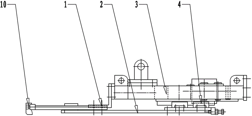
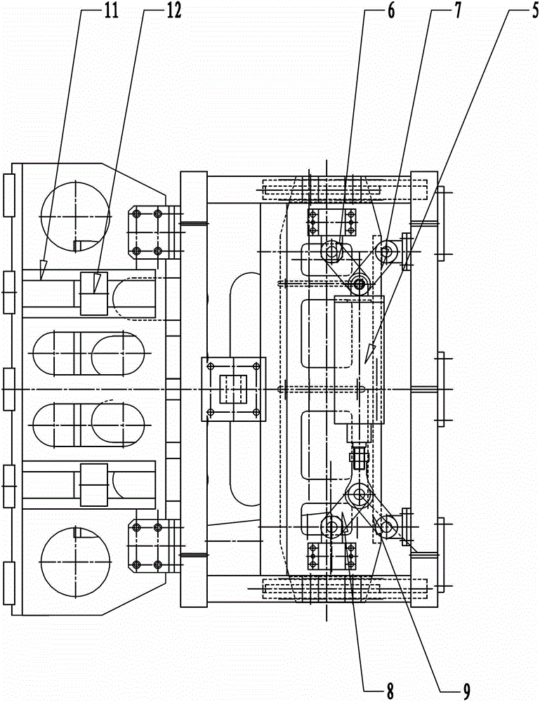
[0013] like Figure 1~2 As shown, the present invention mainly includes a hook plate 1, a clamping plate 2, a mounting bracket 3, a clamping plate slider 4, a clamping cylinder 5, a first clamping rod 6, a second clamping rod 7, a third clamping rod Rod 8, fourth clamping rod 9, sliding groove 11 and sliding guide block 12.

[0014] The front end of the mounting bracket 3 is connected to the hook plate 1 by bolts, and the front end of the hook plate 1 is provided with a plurality of hooks 10 . The hook plate 1 is provided with a slide groove 11 .

[0015] The clamping plate slider 4 is fixed on the clamping plate 2, and the clamping plate slider 4 is slidably installed on the lower end of the mounting bracket 3. The front end of the clamping plate 2 is provided with a sliding guide block 12 , and the sliding guide block 12 is embedded in the sliding...


PUM


Abstract

The invention relates to a clamping device, in particular to a steel grating plate clamping device which comprises a hook plate, a clamping plate, an installation support, a clamping plate slider, a clamping cylinder, a first clamping rod, a second clamping rod, a third clamping rod, a fourth clamping rod, a sliding chute and a sliding guide block. The sliding guide block is arranged at the front end of the clamping plate and inserted into the sliding chute and can slide in the sliding chute. The front end of the first clamping rod is rotatably connected with the clamping plate slider, the back end of the first clamping rod is respectively connected with the second clamping rod and a cylinder body of the clamping cylinder through a pin shaft, the back end of the second clamping rod is rotatably connected with the installation support, the front end of the third clamping rod is rotatably connected with the clamping plate slider, and the back end of the third clamping rod is connected with the fourth clamping rod and a piston rod of the clamping cylinder through a pin shaft, and the back end of the fourth clamping rod is rotatably connected with the installation support. The steel grating plate clamping device is simple, compact and reasonable in structure; reliable in clamping and capable of avoiding error accumulation; convenient to maintain; and capable of avoiding oil leakage apt to happen due to oil cylinder clamping.

Description

technical field [0001] The invention relates to a clamping device, in particular to a steel grating clamping device. Background technique [0002] With the development of the economy, gratings or steel gratings are becoming more and more popular in industries such as petroleum, shipbuilding, construction, mining, public roads, energy and decoration. [0003] Traditionally, a stepping device is used to clamp the steel grating up and down, and an oil cylinder is used to push the clamp to the stepping distance, and then release the clamp to return to the starting point. This reciprocating pinch method has poor stepping accuracy, resulting in cumulative errors exceeding the national standard; at the same time, the use of oil cylinders to clamp easily produces oil leakage. Contents of the invention [0004] The object of the present invention is to overcome the above disadvantages, thereby providing a steel grating clamping device with good clamping performance, simple structu...

Claims


Application Information

Patent Timeline
Patent Type & Authority Patents(China)
IPC IPC(8): B23Q7/00
Inventor 胡晓袁彬彬吴克夏冬彭友平
Owner WUXI WEIHUA ELECTRIC WELDING MFG
Learn More