
Two-way control stop lamp switch

A brake lamp and switch technology, applied in the direction of electric switches, circuits, electrical components, etc., can solve the problems of inconvenient assembly and complicated switch structure, and achieve the effect of reliable performance, simple structure and reliable function

Inactive Publication Date: 2013-02-20
昌辉汽车电器(黄山)股份公司
View PDF6 Cites 4 Cited by
  • Summary
  • Abstract
  • Description
  • Claims
  • Application Information

AI Technical Summary

Problems solved by technology

[0004] The purpose of the present invention is to provide a dual-way control brake light switch, which solves the problems that the existing dual-way control brake light switch has a complicated structure and inconvenient assembly

Method used


Image

  • Two-way control stop lamp switch
  • Two-way control stop lamp switch

Examples


Embodiment Construction

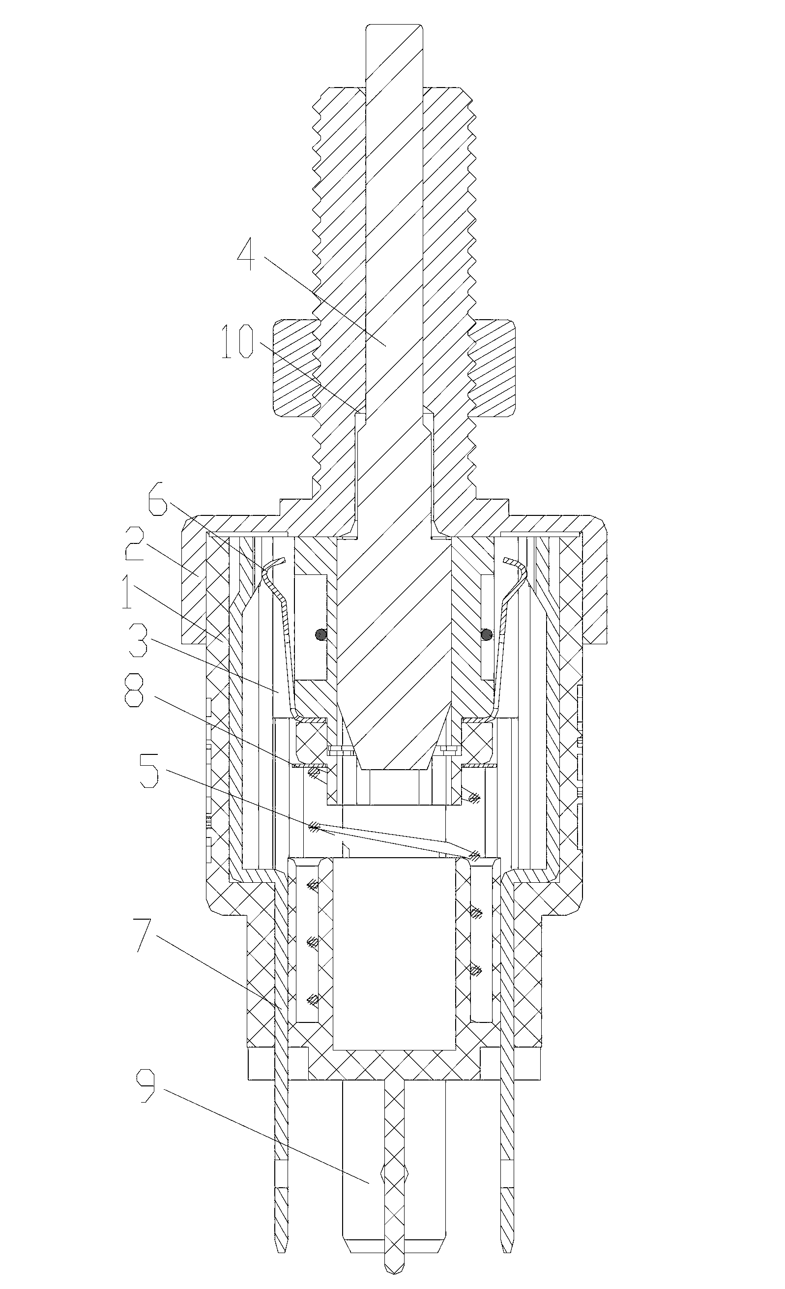
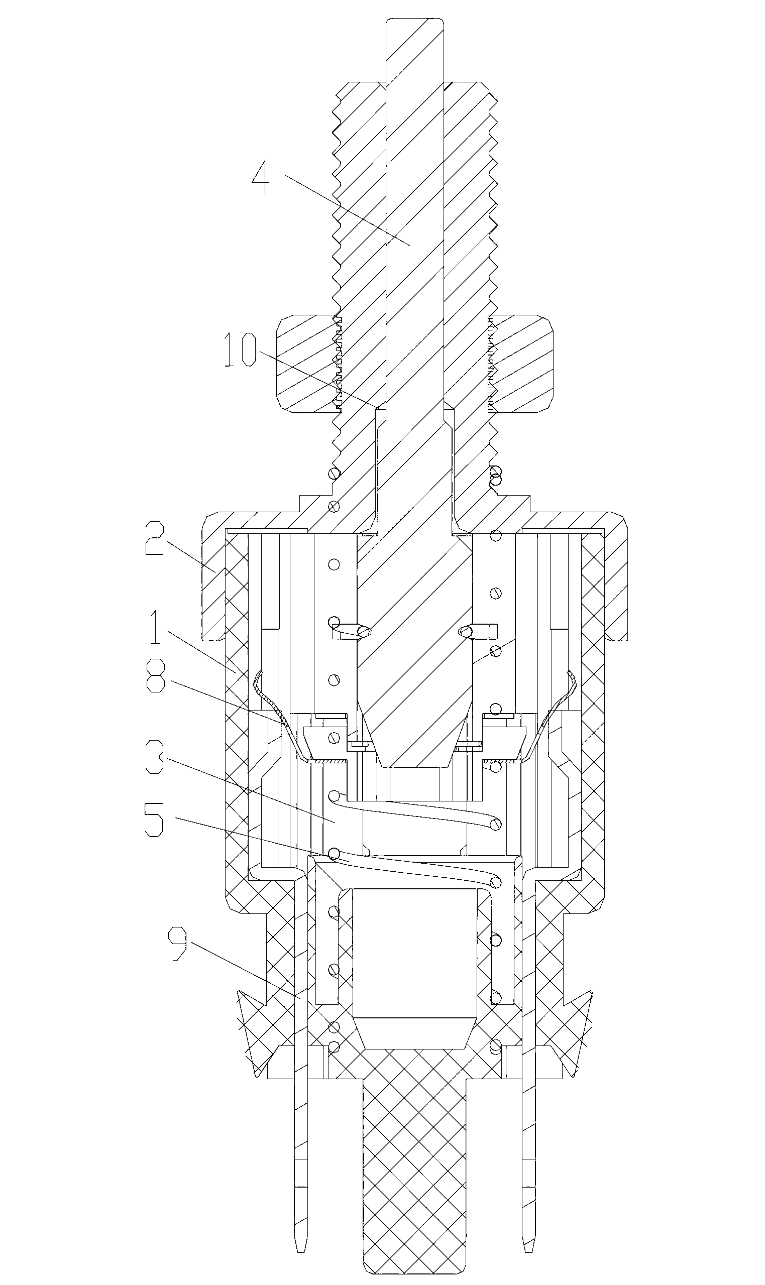
[0015] Examples, please refer to figure 1 and figure 2 , as shown in the figure, a two-way control brake light switch, including a base 1, a fixed seat 2 buckled on the base 1, an inner cavity 3 is formed between the base 1 and the fixed seat 2, and is set in the inner cavity 3 The push rod assembly 4, one end of the push rod assembly 4 protrudes from the fixed seat 2, and a compression spring 5 is arranged between the push rod assembly 4 and the base 1; a cylinder is arranged on the base 1, and one end of the compression spring 5 is covered It is arranged on the cylinder, and one end is sleeved on the push rod assembly 4 . A first movable contact piece 6 is arranged on the push rod assembly 4, and a first static contact piece 7 which cooperates with the first movable contact piece 6 is correspondingly provided in the inner cavity 3; A second movable contact piece 8 is arranged below the first movable contact piece 6 , and a second static contact piece 9 which cooperates wi...


PUM


Abstract

The invention discloses a two-way control stop lamp switch which comprises a base, a fixed seat, an inner cavity, a push rod assembly and a pressure spring, wherein the fixed seat is pressed on the base; the inner cavity is formed between the base and the fixed seat; the push rod assembly is arranged in the inner cavity; one end of the push rod assembly extends out of the fixed seat; the pressure spring is arranged between the push rod assembly and the base; the push rod assembly is provided with a first dynamic contact; the inner cavity is correspondingly provided with a first static contact matched and conductive with the first dynamic contact; a second dynamic contact is arranged on the push rod assembly and below the first dynamic contact; and a second static contact matched and conductive with the second dynamic contact is correspondingly arranged in the inner cavity. According to the invention, resetting is realized by using the pressure spring in such a way that the first dynamic contact and the second dynamic contact are fixed on the push rod assembly; thus, the two-way control stop lamp switch disclosed by the invention has the advantages of simple structure, convenience inassembly and more reliable function.

Description

technical field [0001] The invention relates to a brake light switch, in particular to a dual-way control brake light switch. Background technique [0002] A brake light switch is installed on the brake pedal bracket. When the brake pedal is stepped on, the switch is turned on, notifying the ECU that the brake has been braked, releasing the torque converter lock-up clutch, and lighting the brake light at the same time, which can also prevent driving The engine shuts off suddenly when the wheel brake locks up. Among the various electrical switches in the car at present, the working mode of the brake light switch of the car is various. At present, there are deficiencies in the brake light switches that are widely used: first, the product involves many parts, cumbersome assembly and difficult to achieve process control; second, the wire and switch are connected by soldering, and the circuit is easily disconnected when the voltage is unstable; The 3rd, function simplification,...

Claims


Application Information

Patent Timeline
Patent Type & Authority Applications(China)
IPC IPC(8): H01H13/16H01H13/28
Inventor 王进丁王正成朱排进李宏志
Owner 昌辉汽车电器(黄山)股份公司
Learn More