Automobile engine wheel train drive system

An automotive engine and drive system technology, applied in engine components, machines/engines, mechanical equipment, etc., to solve problems such as fuel consumption, overall engine performance decline, and impact

Active Publication Date: 2013-02-20
GREAT WALL MOTOR CO LTD
View PDF7 Cites 5 Cited by
  • Summary
  • Abstract
  • Description
  • Claims
  • Application Information

AI Technical Summary

Problems solved by technology

It can be seen that the crankshaft is the main driving part of the automobile engine wheel train. Because the engine crankshaft is subject to the combined action of periodically changing forces and moments (including torque and bending moment), coupled with the elasticity of the crankshaft itself and the crankshaft, balance weight, piston, etc. Due to the inertia of the mass of moving parts such as connecting rods, the crankshaft will experience free torsional vibration and forced torsional vibration relative to the flywheel; It is assembled concentrically. When the engine is working normally, the exciting vibration generated by the working characteristics of the valve train, high-pressure oil pump and generator and other auxiliary devices will have a serious impact on the engine crankshaft and gear train (such as noise, vibration, friction loss, power loss, etc.) loss, fuel consumption, life, etc.), leading to a decline in the overall performance of the engine

Method used


Image

  • Automobile engine wheel train drive system
  • Automobile engine wheel train drive system
  • Automobile engine wheel train drive system

Examples


Embodiment Construction

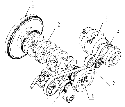
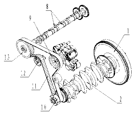
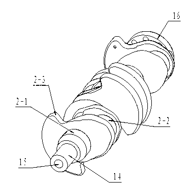
[0022] See Figure 1, figure 2 , image 3 , the present invention includes a crankshaft 2, a timing wheel drive pulley 10, an auxiliary device wheel drive pulley 6 and a dual-mass flywheel 1, and the crankshaft 2 is provided with a main journal 2-1, a bell crank 2-2 and a balance Block 2-3, the timing wheel train drive pulley 10 is installed at the bolt mounting hole 15 of the timing wheel train drive pulley mounting journal at the front end of the crankshaft through bolts, and the dual-mass flywheel 1 is installed at the rear end of the crankshaft 2 through bolts. On the dual-mass flywheel mounting disc 16, timing belt 11 is wound on each pulley of the timing wheel train, and they form the timing train (such as figure 2 shown); the auxiliary device wheel drive pulley 6 is installed on the front end of the timing wheel drive pulley 10 through bolts, and the auxiliary device wheel belt 5 is wound on each pulley of the auxiliary device wheel train, which form the auxiliary dev...


PUM


Abstract

The invention discloses an automobile engine wheel train drive system which comprises a crankshaft, a timing wheel train drive belt wheel, an auxiliary device wheel train drive belt wheel and a dual-mass flywheel, wherein the crankshaft is provided with a main journal, a crank throw and a balance weight; the timing wheel train drive belt wheel is mounted on a timing wheel train drive belt wheel mounting journal at the front end of the crankshaft; the timing wheel train drive belt wheel mounting journal is an eccentric mounting structure relative to the main journal; the auxiliary device wheel train drive belt wheel is mounted at the front end of the timing wheel train drive belt wheel; and the dual-mass flywheel is mounted at the rear end of the crankshaft. The system disclosed by the invention reduces the shock excitation amplitude of an engine wheel train, reduces the oscillating quantity of the belt and the dynamic tension of the belt, prolongs the service life of the parts of the engine wheel train, reduces the operation noise of the wheel train and the frictional loss and power loss, and improves the comprehensive performance of the engine.

Description

technical field [0001] The invention relates to an engine wheel train driving system, in particular to an automobile engine wheel train driving system capable of weakening the excitation generated by a valve mechanism and an engine auxiliary device and ensuring smooth operation of the engine, and belongs to the technical field of combustion engines. Background technique [0002] The automobile engine gear train generally includes a timing gear train, an auxiliary gear train and a flywheel, wherein the timing gear train and the auxiliary gear train are arranged at the front end of the engine, and the flywheel is installed at the power output end of the engine crankshaft. When the engine is started, the flywheel is driven by the starter to rotate, and then the crankshaft, piston, and valve mechanism are driven by the flywheel, and the torque is transmitted to the engine auxiliary device. When the engine is in normal working condition, the crankshaft drives the timing gear trai...

Claims


Application Information

Patent Timeline
Patent Type & Authority Applications(China)
IPC IPC(8): F02B61/06F02B75/06F02B67/06F01L1/348
Inventor 朱泮桥屈伟边锋赵亮孟凡兴李剑
Owner GREAT WALL MOTOR CO LTD
Why Eureka
Try Eureka