
Flash welding forming method of iron-based superalloy thin-wall ring member

A technology of iron-based superalloys and superalloys, applied in welding equipment, resistance welding equipment, metal processing equipment, etc., can solve problems such as scrapped weldments, flash stop, affecting continuous welding and weld quality, and achieves good performance Effect

Active Publication Date: 2013-02-20
GUIZHOU ANDA AVIATION FORGING
View PDF5 Cites 8 Cited by
  • Summary
  • Abstract
  • Description
  • Claims
  • Application Information

AI Technical Summary

Problems solved by technology

However, in the process of welding thin-walled rings such as iron-based superalloy thin-walled rings by flash welding, if the distance between the two ends of the ring blank weld is not well controlled, the flash will stop, which will affect the continuous welding and welding. seam quality, in serious cases, the weldment will be scrapped

Method used


Image

  • Flash welding forming method of iron-based superalloy thin-wall ring member
  • Flash welding forming method of iron-based superalloy thin-wall ring member
  • Flash welding forming method of iron-based superalloy thin-wall ring member

Examples


specific Embodiment approach

[0037] The main chemical element content (percentage by weight) of the alloy is: C content ≤ 0.06%, Si content 0.07% ~ 0.35%, Ni content 35.0% ~ 40.0%, Co content 12.0% ~ 16.0%, Nb+ Ta content 4.3%~5.2%, Ti content 1.3%~1.8%, Cr content ≤1.00%, Al content ≤0.20%, Mn content ≤1.00%, Cu content ≤0.50%, B content ≤0.012 %, S content ≤ 0.015%, P content ≤ 0.015%, and the balance is Fe.

[0038] The flash welding forming process steps of the alloy thin-walled ring are as follows:

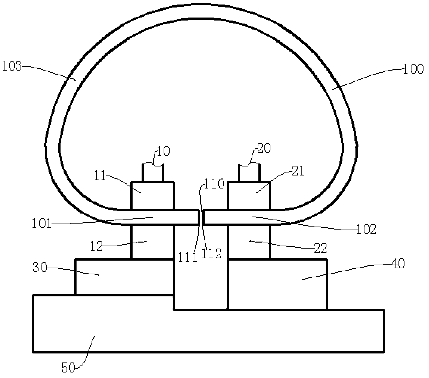
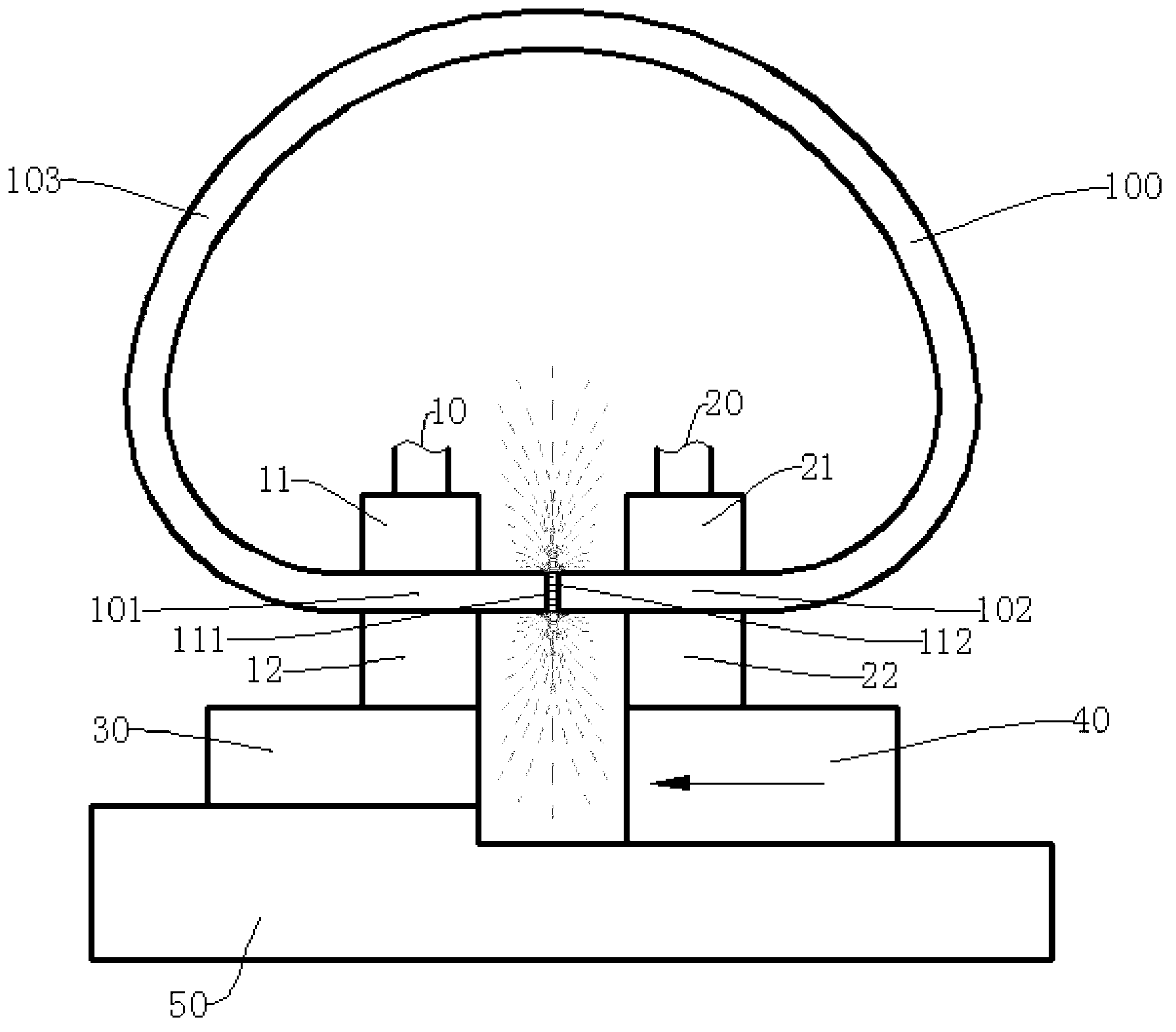
[0039] Step 1: Install the computer. Such as figure 1As shown, the GH907 alloy D-shaped ring blank with an opening is loaded into a flash butt welding machine with a power of 1000KVA. The D-shaped ring blank is composed of a left straight edge 101, a right straight edge 102 and an arc edge 103. The side of the opening 110 corresponding to the left straight side 101 has a left end surface 111 , and the side corresponding to the right straight side 102 has a right end surface 112 . When installing, put...


PUM


Abstract

The invention discloses a flash welding forming method of an iron-based superalloy thin-wall ring member, which comprises the steps of: loading a D type ring blank with an opening in a welder, starting the welder to close the opening of the preheated ring blank, applying a 7-18V voltage between two poles of the welder to ensure that the left end face and the right end face of the opening of the ring blank are heated and molten through a flash current with the current density of 30A / mm<2>-200A / mm<2> to form a lintel, exploding to form a flash, wherein the flash burning loss speed of the ring blank is 2.4mm-4.8mm / s; driving the right end face of the ring blank to make an accelerated feeding movement towards the left end face at an initial speed of 1.2mm / s-2.4mm / s and an acceleration of 0.4mm / s<2>-0.8mm / s<2> so as to ensure that the distance between the left end face and the right end face is not more than 8mm; and after the flash is completed, driving a right straight side of the ring blank to move at a high speed towards a left straight side of the ring blank to ensure that the left end face and the right end face collide with each other under the action of an upsetting force of 12kN-17kN to form the flash welding thin-wall ring member, and keeping the pressure for 15s-25s under the action of the upsetting force. The method can ensure that the flash process is continuously and stably carried out, thereby improving the weld quality.

Description

technical field [0001] The invention relates to a welding method, in particular to a flash welding forming method of an iron-based superalloy thin-walled ring. Background technique [0002] With the increasing demand for rings in industries such as aviation, aerospace, ships, gas turbines, wind energy, nuclear energy, and bearings, rings formed by traditional rolling methods not only waste a lot of materials due to large machining allowances and low material utilization , but also keeps the cost of ring parts high. The ring parts produced by the flash welding process have less machining allowance, high material utilization rate, and greatly reduce the cost, which is conducive to the development of ring forming technology in the direction of precision forming technology. [0003] The Chinese invention patent specification CN 1233548A published on November 3, 1999 discloses a flash welding process for aluminum alloy wheels of automobiles and motorcycles. The technological pro...

Claims


Application Information

Patent Timeline
IPC IPC(8): B23K11/04
Inventor 肖志翔魏志坚蒲思洪邹朝江何冰彭泉兴郭浩
Owner GUIZHOU ANDA AVIATION FORGING
Learn More