Permanent magnet breaker operation mechanism provided with emergency separating brake device

A permanent magnet circuit breaker and operating mechanism technology, applied in the direction of high-voltage air circuit breakers, circuits, electrical components, etc., can solve the problems of increased mechanical failure points, debugging of key components, small maintenance space, and large transmission losses, etc., to achieve reduction The effect of managing costs, simplifying the transmission link of the mechanism, and improving the operation reliability

Active Publication Date: 2013-02-13
NINGXIA LICHENG ELECTRIC GROUP
View PDF5 Cites 0 Cited by
  • Summary
  • Abstract
  • Description
  • Claims
  • Application Information

AI Technical Summary

Problems solved by technology

(2) Using part of the characteristics of the spring mechanism for reference, multiple sets of single crank arms are used in the transmission link to obtain torque output; (3) The layout of the mechanism box is not particular, and the installation position of the permanent magnet mechanism and power electronic devices is unreasonable; such The problems in the design are: (1) The emergency opening accessories are not easy to manage, which is easy to cause power operation accidents; (2) The transition of multiple sets of single crank arms causes more transmission losses and increases mechanical failure points; (3) The mechanism box is messy, and the key Small space for component debugging and maintenance, resulting in high user management costs

Method used


Image

  • Permanent magnet breaker operation mechanism provided with emergency separating brake device
  • Permanent magnet breaker operation mechanism provided with emergency separating brake device
  • Permanent magnet breaker operation mechanism provided with emergency separating brake device

Examples


Embodiment 1

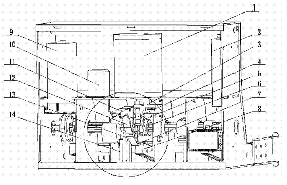
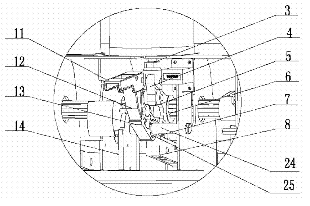
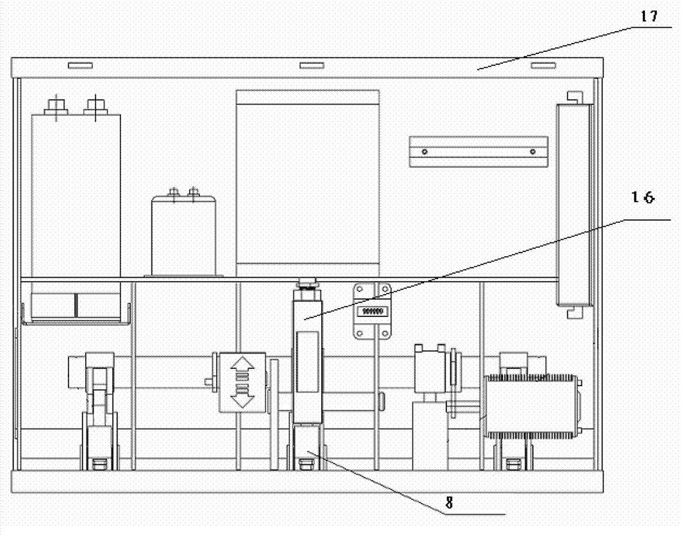
[0019] An operating mechanism of a permanent magnet circuit breaker with its own emergency opening device, comprising a handle base 13, a permanent magnet mechanism 1, a permanent magnet mechanism controller 2, a closing capacitor 9, an opening capacitor 10, a double-headed crank arm 5, Buffer, main shaft 6, upper movable connector 4, lower movable connector 7, mechanism box 17, output connecting rod. The handle base 13 is integrated with the permanent magnet mechanism 1, which is convenient for operation and management. Handle base 13, folding handle 11, ratchet 12, reset limit device 14 etc. constitute emergency opening device 16, when emergency opening, the pawl 12 on the upper section of handle base 13 falls naturally due to gravity and the V-shaped steps on the lower section of handle base 13 Bite to form a stable triangular frame, and the triangular frame is used as an extended moment arm to assist opening.

[0020] After the gate opening is completed, the handle base 1...


PUM


Abstract

The invention relates to the field of permanent high-pressure vacuum circuit breakers, in particular to a permanent magnet breaker operation mechanism provided with an emergency separating brake device. The permanent magnet breaker operation mechanism comprises a mechanism box (17) and a main shaft (6) which is arranged inside the box. The permanent magnet breaker operation mechanism is characterized in that double-head connecting lever (5) is fixedly arranged on the main shaft (6), one end of the double-head connecting lever (5) is in transmission connection with a permanent magnet output connection rod (3) through an upper moving connection part (4), and the other end of the double-head connecting lever (5) is in transmission connection with a transmission output connection rod (8) through a lower moving connection part (7). The permanent magnet breaker operation mechanism further comprises a handle seat (13), wherein one end of the handle seat (13) is sleeved on a locating shaft (24) through a bearing (25). The permanent magnet breaker operation mechanism is provided with the emergency separating brake device which is in integration with the permanent magnet breaker operation mechanism, the double-head connecting lever is designed, operation reliability of a permanent magnet breaker is improved, mechanism transmission links are simplified, and management cost of users are lowered.

Description

technical field [0001] The invention relates to the field of permanent magnet high-voltage vacuum circuit breakers, in particular to an operating mechanism of a permanent magnet circuit breaker with an emergency opening device. Background technique [0002] The operating mechanism of the traditional high-voltage vacuum circuit breaker mainly adopts a spring mechanism, which has many parts and complicated transmission, so there are many fault sources and a high failure rate during operation, which brings a lot of repair and maintenance workload to the user unit. The vacuum circuit breaker with permanent magnet mechanism that has appeared in recent years has attracted much attention due to its advantages of fewer main moving parts, reliable operation, and better coordination of mechanical characteristics and vacuum circuit breaker than traditional operating mechanisms. The permanent magnet mechanism adopts the principle of electromagnetic drive and permanent magnet retention t...

Claims


Application Information

Patent Timeline
Patent Type & Authority Applications(China)
IPC IPC(8): H01H33/666
Inventor 牛广军姬涛李发红丁立科
Owner NINGXIA LICHENG ELECTRIC GROUP
Why Eureka
Try Eureka