


Quick Research
Generate reliable direction feasibility study reports for your R&D in just a few steps.

Technical Q&A
Discover and master advanced knowledge NOW. Basics, ideas, possibilities, all at once.

Find Solutions
As an expert in R&D theories, this can generate solutions to your technical problems instantly.

Evaluate Feasibility
Analyze your overall solution with one click, know your potential R&D risks in advance.

Monitor Landscape
Get weekly tech updates, stay abreast of the latest tech innovations and key insights.
A full-computer glove machine gear shaft control device
A glove machine and full computer technology, applied in textiles and papermaking, knitting, weft knitting, etc., can solve the problems of complex assembly, cumbersome operation, and high cost, achieve convenient assembly and maintenance, reduce manufacturing costs, and reduce the number of parts Effect
- Summary
- Abstract
- Description
- Claims
- Application Information
AI Technical Summary
Problems solved by technology
Method used
Image

Examples
Embodiment 1
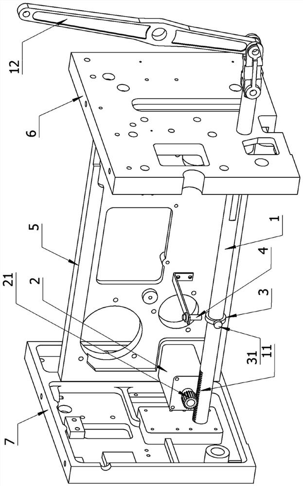
[0023] like figure 1 , figure 2 As shown, a full-computer glove machine gear shaft control device includes: a gear shaft 1, a middle wall plate 5, a left wall plate 7, a right wall plate 6, a stepping motor 2, an induction coil 3, and an inductor 4; The two ends of the middle wall panel 5 are fixed with a left wall panel 7 and a right wall panel 6, and are assembled in an I-shape; a stepping motor 2 is installed on the middle wall panel 7, and a motor gear 21 is fixed on the rotating shaft of the stepping motor 2;
[0024] The gear shaft 1 can move freely through the through holes on the left wall plate 7 and the right wall plate 6. The left end of the gear shaft 1 is partially provided with a rack 11, which is connected with the motor gear on the shaft head of the stepping motor 2. 21 is adapted. When the stepping motor 2 rotates, the motor gear 21 will drive the gear shaft 1 to move left and right through the rack 11; The upper end of the arm 12 is connected with the mach...
Embodiment 2
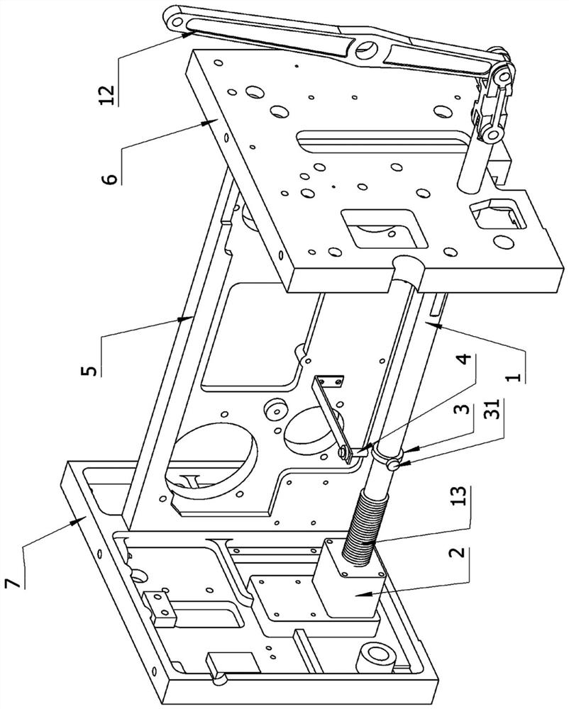
[0034] see Figure 5 , the basic structure is the same as that of Embodiment 1, the difference is: the stepping motor 2 fixed on the middle wall panel 5 is installed on the left wall panel 7, and the motor gear fixed on the rotor of the stepping motor 2 is cancelled. 21. The rack 11 on the gear shaft 1 is cancelled; the outer thread 13 is set on the left circumference of the gear shaft 1; the rotor of the stepping motor 2 is hollow (special motors can be customized by the motor factory) , do not need to be introduced in detail), the interior of the hollow rotor is provided with an internal thread, which is equivalent to a large nut. The internal thread of the hollow rotor is matched with the external thread 13 on the gear shaft 1. When the hollow rotor of the stepping motor 2 rotates , the gear shaft 1 moves left and right under the drive of the external thread 13 . The advantages of this setting are: the thread drive is more precise and meticulous than the rack drive, the ma...
Embodiment 3
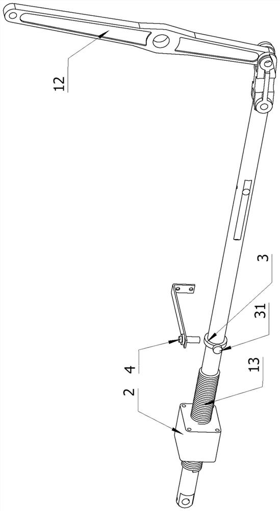
[0036] see Image 6 , the basic structure is the same as that of the first embodiment, the difference is: the stepper motor 2 fixed on the middle wall plate 5 is installed on the left wall plate 7, and the rack 11 on the gear shaft 1 is cancelled; An external thread 13 is set on the left circumference of the gear shaft 1; a large gear 8 is also pinned on the left wall plate 7 below the stepper motor 2, and the motor gear 21 and The large gear 8 is adapted, and the stepping motor 2 can drive the large gear 8 to rotate; there is a through hole in the middle of the large gear 8, and an internal thread is set in the through hole; the gear shaft 1 passes through the threaded hole in the middle of the large gear 8, and the large gear 8 The internal thread of the gear shaft 1 is adapted to the external thread 13 of the gear shaft 1; when the stepping motor 2 rotates, the motor gear 21 drives the large gear 8 to rotate, and the internal thread of the large gear 8 drives the external t...
PUM
 Abstract
Description
Claims
Application Information
 - R&D Engineer
- R&D Manager
- IP Professional
- Industry Leading Data Capabilities
- Powerful AI technology
- Patent DNA Extraction
Browse by: Latest US Patents, China's latest patents, Technical Efficacy Thesaurus, Application Domain, Technology Topic, Popular Technical Reports.
© 2024 PatSnap. All rights reserved.Legal|Privacy policy|Modern Slavery Act Transparency Statement|Sitemap|About US| Contact US: help@patsnap.com