
Central multi-drive transmission device of elongated output shaft of speed reducer

A transmission device and reducer technology, applied in the direction of transmission device, gear transmission device, transmission box, etc., can solve the problems of low transmission efficiency, time-consuming and inconvenient, long production cycle, etc., to reduce additional losses, keep the environment clean, and improve transmission efficiency high effect

Inactive Publication Date: 2013-02-13
淮北重科矿山机器有限公司
View PDF10 Cites 1 Cited by
  • Summary
  • Abstract
  • Description
  • Claims
  • Application Information

AI Technical Summary

Problems solved by technology

The number of multi-point drive transmission mechanisms is large and the torque is large; due to the needs of structure and strength, the size of the transmission hub is large, the distance between the plane on the cover plate of the central transmission box and the tooth surface of the central rotary large gear is relatively large, and the output shaft of the ordinary reducer is small. The gears cannot mesh with the large gears. In order to realize the normal meshing of the large and small gears, people use intermediate transition transmission, which has low transmission efficiency, high cost and long production cycle.
Moreover, when changing the oil of the reducer, it is necessary to remove the reducer and replace the lubricating oil of the reducer, which is time-consuming and inconvenient

Method used


Image

  • Central multi-drive transmission device of elongated output shaft of speed reducer

Examples


Embodiment Construction

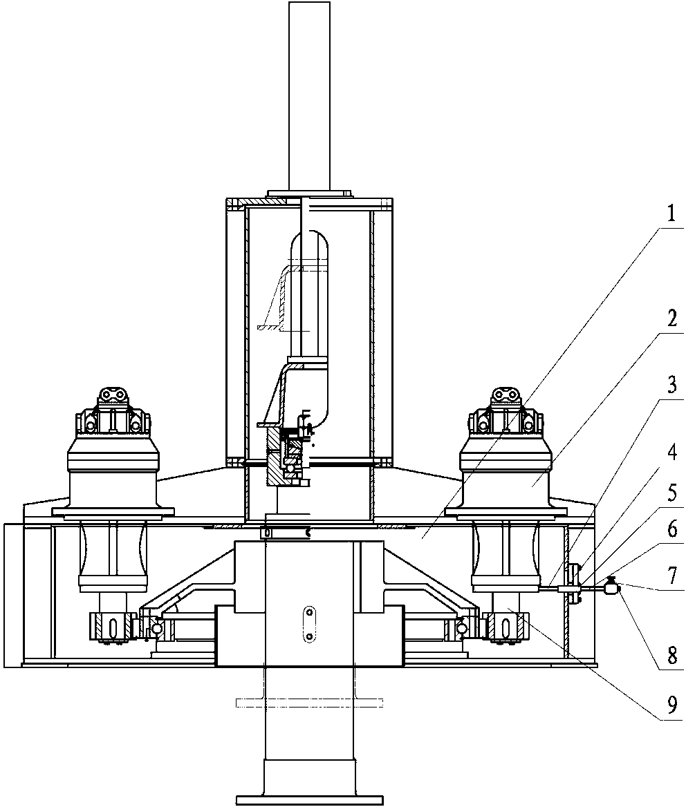
[0021] As shown in the drawings, the present invention includes a transmission box 1, a reducer 2, an oil discharge pipe 3 in the box, a combination hole cover 4, a plate-through pipe joint 5, an oil discharge pipe 6 outside the box, a stop valve 7, an oil plug 8, an extended Output shaft 9 etc.

[0022] The reducer 2 with the extended output shaft 9 is installed on the transmission box 1, and its casing is correspondingly lengthened. The middle part of the casing has a mounting flange, which is installed on the transmission box 1. The parts below the reducer 2 flange are The casing enters the center transmission gearbox; a bearing is installed at the end of the casing to withstand the additional force generated by the lengthening of the shaft, improve the working condition of the reducer 2, and make the force condition of the output shaft 9 of the reducer reasonable ;The pinion gear is assembled at the end of the extended output shaft 9 below the casing, and it meshes with th...


PUM


Abstract

The invention discloses a central multi-drive transmission device of an elongated output shaft of a speed reducer. The central multi-drive transmission device of the elongated output shaft of the speed reducer resolves the problems that an existing device needs middle transition transmission, and is low in efficiency and high in cost, and is characterized in that a machine shell of the speed reducer is elongated, the elongated output shaft is arranged, a pinion is arranged at the shaft end of the elongated output shaft in a matched mode, the pinion is directly meshed with the a big gear, and the speed reducer is provided with an oil extraction pipeline and comprises a box inside oil extraction pipe, a combined hole cover, a plate-penetrating pipe connector, a box outside oil extraction pipe, a stop valve, an oil blockage, and the like. According to the central multi-drive transmission device of the elongated output shaft of the speed reducer, the pinion arranged at the shaft end of the elongated output shaft is utilized to directly transmit the big gear, and therefore the transmission efficiency is high; when the arranged oil extraction pipeline replaces oil, the detachment of the speed reducer is not needed, and the replacement is convenient; and the combined hole cover, the plate-penetrating pipe connector and the like are combined to form a detachable pipeline, so that the oil extraction pipeline does not affect the replacement of the speed reducer.

Description

technical field [0001] The present invention relates to a transmission device, more specifically to a multi-point drive transmission device for a central drive thickener. Background technique [0002] The central multi-point drive system is to distribute three or more reducers evenly on the meshing circle of the large gear, each of which rotates independently, and the pinion at the output shaft end of the reducer drives the large gear together using the principle of self-synchronization. The number of multi-point drive transmission mechanisms is large and the torque is large; due to the needs of structure and strength, the size of the transmission hub is large, the distance between the plane on the cover plate of the central transmission box and the tooth surface of the central rotary large gear is relatively large, and the output shaft of the ordinary reducer is small. The gears cannot mesh with the large gears. In order to realize the normal meshing of the large and small ...

Claims


Application Information

Patent Timeline
Patent Type & Authority Applications(China)
IPC IPC(8): F16H57/02F16H57/04F16H1/22
Inventor 方存刚丁配银方正军丁言威任磊
Owner 淮北重科矿山机器有限公司
Learn More