
AC-LED fluorescent lamp

A technology of AC-LED and fluorescent lamps, applied in the field of lighting, can solve the problems of AC-LED stroboscopic phenomenon, withstand voltage problem, stroboscopic and other problems, and achieve the effects of avoiding stroboscopic phenomenon, reducing costs and high power factor

Inactive Publication Date: 2013-02-06
58TH RES INST OF CETC +1
View PDF6 Cites 6 Cited by
  • Summary
  • Abstract
  • Description
  • Claims
  • Application Information

AI Technical Summary

Problems solved by technology

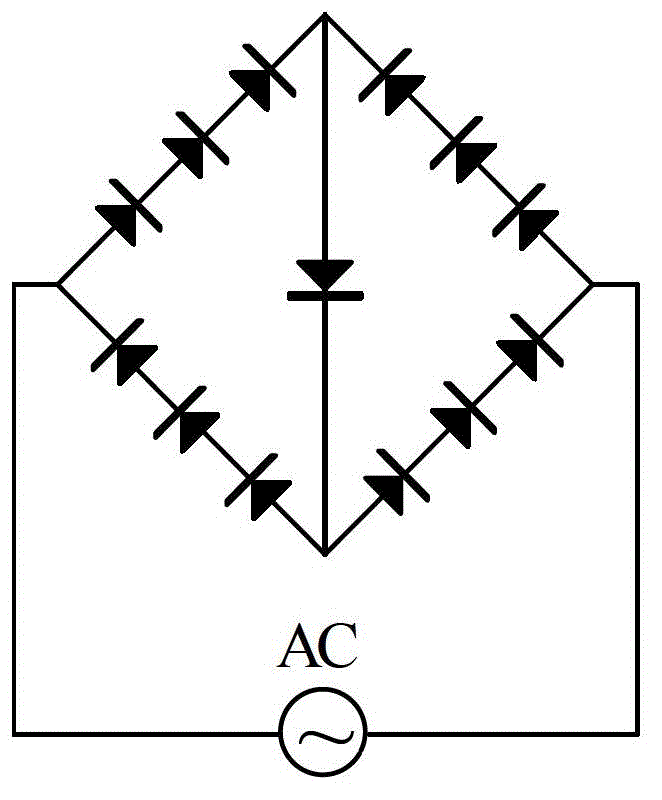
[0009] (2) Stroboscopic phenomenon of AC-LED with bridge structure
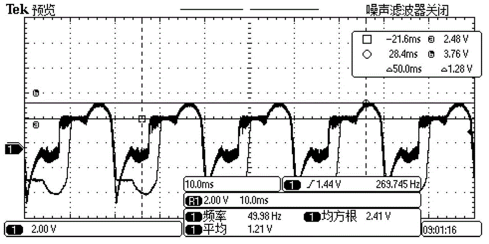
When the input voltage is AC30.5V, the input current is about 30mA (the test result of UI3000 electronic ballast comprehensive performance tester), and the typical waveform of each LED chip when it is working refers to figure 2 , the waveform period is 20ms, the protruding part of the waveform between the cursors corresponds to the conduction of the LED chip, the voltage value ranges from 2.48V to 3.76V, and the conduction time is about 6ms, which is close to one-third of a cycle, that is, within a power cycle, The LED chip stays on for less than one-third of the time, so there is a strobe phenomenon
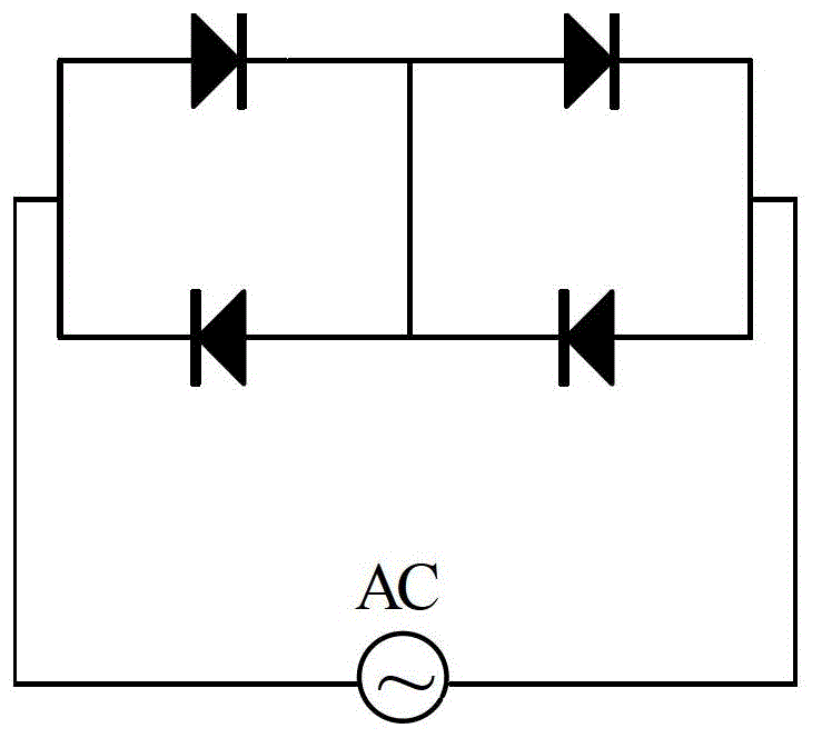
When the input voltage is AC26.4V, the input current is about 30mA (the test result of UI3000 electronic ballast comprehensive performance tester), and the typical waveform of each LED chip when it is working can be referred to Figure 4 , the waveform period is 20ms, the protruding part of the waveform between the cursors corresponds to the conduction of the LED chip, the voltage value ranges from 2.44V to 3.72V, and the conduction time is about 6ms, which is close to one-third of a cycle, that is, within a power cycle , the LED chip stays on for less than one-third of the time, so the stroboscopic phenomenon also occurs
[0011] (3) The withstand voltage of the product

Method used


Image

  • AC-LED fluorescent lamp
  • AC-LED fluorescent lamp
  • AC-LED fluorescent lamp

Examples


Embodiment Construction

[0041] The technical solutions of the present invention will be described in detail below in conjunction with the accompanying drawings.

[0042] The invention provides an AC-LED fluorescent lamp, which uses a power drive circuit to convert high voltage into pulsating DC high voltage, and then connects in series an AC-LED array composed of low-voltage and low-power LED chips that meet the requirements of voltage impedance matching and optical parameters, which can make AC High voltage is directly applied to low-voltage low-power LED chips for mainstream applications in the market. The AC-LED fluorescent lamp includes a power drive circuit, an AC-LED array and a kit, which will be introduced separately below.

[0043] It has been analyzed above that the figure 1 and image 3 The AC-LED integrated array shown has stroboscopic phenomenon, because the conduction time of the LED in a power cycle is only one-third of the power cycle, and the short conduction time causes visual str...


PUM


Abstract

The invention discloses an AC (Alternating Current)-LED (Light-emitting Diode) fluorescent lamp which comprises a power supply drive circuit, an AC-LED array and a kit, wherein the kit comprises an aluminium substrate, a radiator and a PC (Poly Carbonate) cover; the input end of the power supply drive circuit is connected with an input power supply; the output end of the power supply drive circuit is connected with the AC-LED array; the AC-LED array comprises at least two LED chips; the LED chips are averagely divided into at least two groups; the LED chips in each group are sequentially connected end to end in series; then all the groups are connected in parallel in the same direction; the LED chips are fixed on the aluminium substrate; the aluminium substrate is fixed on the radiator; and the PC cover is fixed on the radiator and arranged outside the AC-LED array in a covering manner. With the adoption of the AC-LED fluorescent lamp, the cost of an LED illumination product can be lowered, and the service life can be prolonged.

Description

technical field [0001] The invention belongs to the field of lighting, in particular to an AC-LED fluorescent lamp. Background technique [0002] At present, the mainstream LED products on the market mainly adopt the low-voltage constant-current DC source power supply method based on a single low-voltage high-power LED chip, so it is called DC-LED, which is characterized by the use of different topologies and different architectures (isolated and non-isolated) type) and integrates APFC, AC-DC converter and various abnormal state protection functions, the DC-LED drive switching power supply converts high-voltage AC power into a low-voltage constant-current DC source suitable for DC-LED use. [0003] The performance of DC-LED drive power directly determines the performance of LED products. With the wide application of DC-LED products, higher requirements are put forward for its performance: high power factor. The APFC circuit must be included in the DC-LED driving switching ...

Claims


Application Information

Patent Timeline
Patent Type & Authority Applications(China)
IPC IPC(8): H05B37/02
Inventor 孙海涛胡南中黄伟李海鸥于宗光
Owner 58TH RES INST OF CETC
Learn More