
Underwater LED visible light communication system

A visible light communication and optical signal technology, applied in the field of optical communication, can solve the problems of low sound propagation speed, large attenuation of electromagnetic waves, and difficult to achieve, and achieve the effect of improving transmission rate, reducing volume, and avoiding interference.

Inactive Publication Date: 2013-02-06
KUANG CHI INST OF ADVANCED TECH +1
View PDF3 Cites 41 Cited by
  • Summary
  • Abstract
  • Description
  • Claims
  • Application Information

AI Technical Summary

Problems solved by technology

Sonar technology is currently the most mature underwater communication technology, but the propagation speed of sound in water is low, less than one-twentieth of the speed of light. Factors such as scattering of sound waves in water, loss of transmission, and interference of echoes also make The development of underwater acoustic equipment is very difficult
At the same time, when communicating with small underwater sensors, it is bulky and consumes more energy
For radio communication, due to the large attenuation of electromagnetic waves in water, it is difficult to realize underwater wireless communication applications. The existing underwater wireless communication systems are limited to shallow sea areas and require huge antenna systems.
Moreover, radio communication may cause interference to the human body and peripheral electronic equipment

Method used


Image

  • Underwater LED visible light communication system
  • Underwater LED visible light communication system
  • Underwater LED visible light communication system

Examples


Embodiment Construction

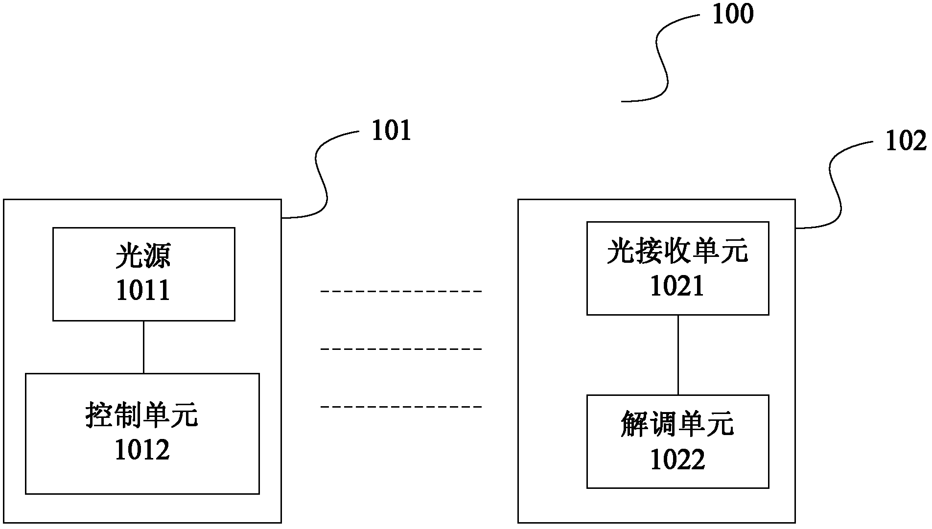
[0028] figure 1 It is a schematic structural diagram of an underwater LED visible light communication system 100 according to a preferred embodiment of the present invention, including a sending device 101 and a receiving device 102 that are placed underwater and are each waterproof and sealed. Regarding the specific sealing method of the sending device 101 and the receiving device 102, for example, it can be placed in a waterproof airtight box, and the materials used can be, for example but not limited to, polycarbonate, ABS (Acrylonitrile Butadiene Styrene, acrylonitrile-butadiene-styrene copolymer) ) resin, glass fiber reinforced polyester or die-cast aluminum. With the advancement of technology, new materials or new sealing methods may also appear, which is not limited in the present invention.

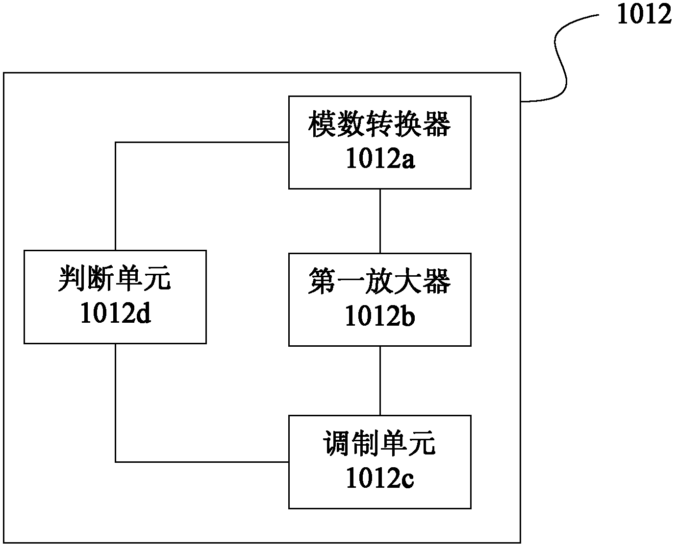
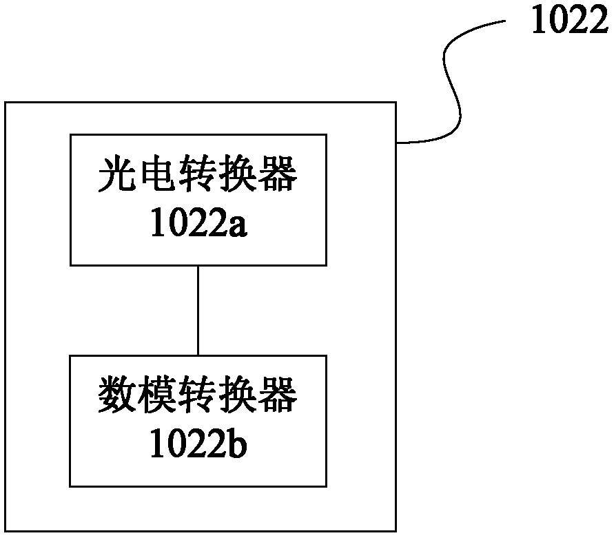
[0029] Such as figure 1 , the sending device 101 includes an LED light source 1011 and a control unit 1012 for modulating the light signal emitted by the LED light source accord...


PUM


Abstract

The invention relates to an underwater LED (light-emitting diode) visible light communication system. The underwater LED visible light communication system comprises a water-proof and sealed transmitting device and a water-proof and sealed receiving device which are placed underwater; the transmitting device comprises a light source and a control unit for modulating a light signal emitted by the light source according to information to be transmitted; and the receiving device comprises a light receiving unit for receiving the modulated light signal from the transmitting device, and a demodulating unit for demodulating the received modulated light signal so as to restore the transmitted information. According to the technical solution, by modulating the transmitted information into the light signal, underwater wireless optical communication is achieved, thus not only improving the transmission rate and reducing the size and attenuation, but also avoiding interference to a human body and surrounding electronic equipment and achieving dual functions of lighting and communication.

Description

technical field [0001] The present invention relates to the field of optical communication, and more specifically relates to an underwater LED visible light communication system. Background technique [0002] Underwater communication technology includes sonar technology and traditional radio communication technology. Sonar technology is currently the most mature underwater communication technology, but the propagation speed of sound in water is low, less than one-twentieth of the speed of light. Factors such as scattering of sound waves in water, loss of transmission, and interference of echoes also make The development of underwater acoustic equipment is very difficult. At the same time, when communicating with small underwater sensors, they are bulky and consume more energy. For radio communication, due to the large attenuation of electromagnetic waves in water, it is difficult to realize underwater wireless communication applications. The existing underwater wireless co...

Claims


Application Information

Patent Timeline
Patent Type & Authority Applications(China)
IPC IPC(8): H04B10/116H04B13/02
Inventor 刘若鹏栾琳刘京京马伟涛李平军
Owner KUANG CHI INST OF ADVANCED TECH
Learn More