
Grid voltage temperature compensation circuit and method, and display device

A technology of temperature compensation circuit and grid voltage, applied in static indicators, instruments, etc., can solve problems such as TFT opening, display failure, and failure to ensure normal operation of display devices, etc., to achieve the effect of improving image quality

Inactive Publication Date: 2013-02-06
HEFEI BOE OPTOELECTRONICS TECH +1
View PDF2 Cites 26 Cited by
  • Summary
  • Abstract
  • Description
  • Claims
  • Application Information

AI Technical Summary

Problems solved by technology

[0006] In the field of display, TFT plays the role of controlling the pixel switch. When the gate voltage of the TFT is not enough to turn on the TFT, the TFT works in the unsaturated region, and the display cannot be performed normally.
Especially in the field of liquid crystal display, liquid crystal display systems are used in more and more fields, and the working environments of liquid crystal display systems are different. The temperature of the working environment may be in the range of -50°C~150°C. The gate voltage of the pixel drive circuit designed in a normal temperature environment is a constant value, which cannot guarantee the normal operation of the display device at a lower temperature
Therefore, the existing display devices cannot overcome the temperature-induced threshold change of the TFT, resulting in insufficient gate voltage to enable the TFT to be turned on, and the displayed image is not normal.

Method used


Image

  • Grid voltage temperature compensation circuit and method, and display device
  • Grid voltage temperature compensation circuit and method, and display device
  • Grid voltage temperature compensation circuit and method, and display device

Examples


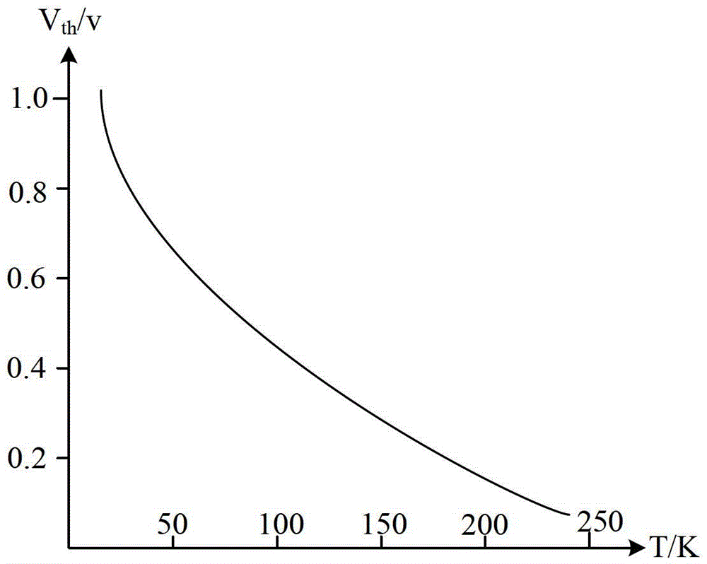
Embodiment Construction

[0029] Embodiments of the present invention provide a gate voltage temperature compensation circuit, a compensation method, and a display device, which are used to implement temperature compensation on the gate voltage of a TFT when the TFT cannot be fully turned on, so as to improve image quality.

[0030] The gate voltage temperature compensation circuit described in the embodiment of the present invention is applicable to the environment where the TFT operates at a relatively low temperature, and it is difficult to turn on the TFT with a preset gate voltage so that the TFT cannot work in a saturation region. This is because the threshold voltage of the TFT in a low-temperature environment becomes larger, it is difficult to fully open, and the TFT cannot work in the saturation region. The gate voltage temperature compensation circuit provided by the embodiment of the present invention can make the TFT that works normally at a certain temperature, In an environment lower than ...


PUM


Abstract

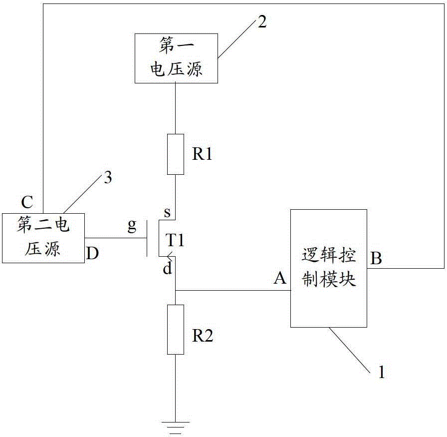
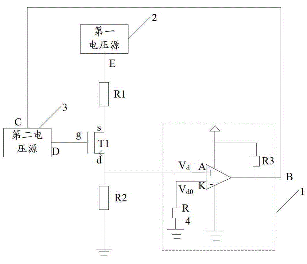
The invention discloses a grid voltage temperature compensation circuit, a grid voltage temperature compensation method and a display device, which are used for realizing grid voltage temperature compensation on a thin film transistor (TFT) when the TFT cannot be started completely and improving the quality of an image. The grid voltage temperature compensation circuit comprises a feedback transistor, a logical control module, a first voltage source and a second voltage source, wherein the grid electrode of the feedback transistor is connected with the output end of the second voltage source; the source electrode of the feedback transistor is connected with the output end of the first voltage source; the drain electrode of the feedback transistor is connected with the input end of the logical control module; the output end of the logical control module is connected with the input end of the second voltage source; and the logical control module is used for comparing the current drain electrode voltage with the reference drain electrode voltage and outputting the comparison result to the second voltage source through the output end, so that the second voltage source performs temperature compensation on the current grid voltage according to the comparison result.

Description

technical field [0001] The invention relates to the technical field of image display driving, in particular to a grid voltage temperature compensation circuit, a compensation method, and a display device. Background technique [0002] In the field of display technology, thin film transistors as switching devices play an important role. [0003] The working principle of a thin film transistor (Thin Film Transistor, TFT) as a switching device is briefly described as follows: [0004] When the gate of the TFT is applied with respect to the ground GND voltage V g (referred to as the gate voltage), an electric field is generated between the gate and the source of the TFT, and the electronic channel formed by the TFT under the action of the electric field makes the source and the drain conduct, and the gap between the gate and the source The forward voltage difference (that is, the threshold voltage V th ) is larger, the conduction channel is wider, and the conduction current i...

Claims


Application Information

Patent Timeline
Patent Type & Authority Applications(China)
IPC IPC(8): G09G3/36G09G3/20
Inventor 王东辉李恒滨马韬黄姗姗汪敏
Owner HEFEI BOE OPTOELECTRONICS TECH
Learn More