
Method for detecting flow rate using ultrasonic waves

A detection method and ultrasonic technology, applied in the measurement of flow/mass flow, ultrasonic/sonic/infrasonic, measurement devices, etc., can solve problems such as affecting measurement accuracy, and achieve self-compensation and avoid effects.

Active Publication Date: 2014-10-22
GL TECH CO LTD
View PDF4 Cites 1 Cited by
  • Summary
  • Abstract
  • Description
  • Claims
  • Application Information

AI Technical Summary

Problems solved by technology

[0010] The purpose of the present invention is to provide a detection method that utilizes ultrasonic waves to detect flow, so as to solve the problem that in the prior art, it is necessary to perform compensation calculations for various environmental factors in order to obtain the true propagation speed C of ultrasonic waves in fluid media. f Technical problems that affect measurement accuracy

Method used


Image

  • Method for detecting flow rate using ultrasonic waves
  • Method for detecting flow rate using ultrasonic waves
  • Method for detecting flow rate using ultrasonic waves

Examples


Embodiment Construction

[0025] Utilize the embodiment of the detection method of ultrasonic detection flow, the detection method in this embodiment comprises the following steps:

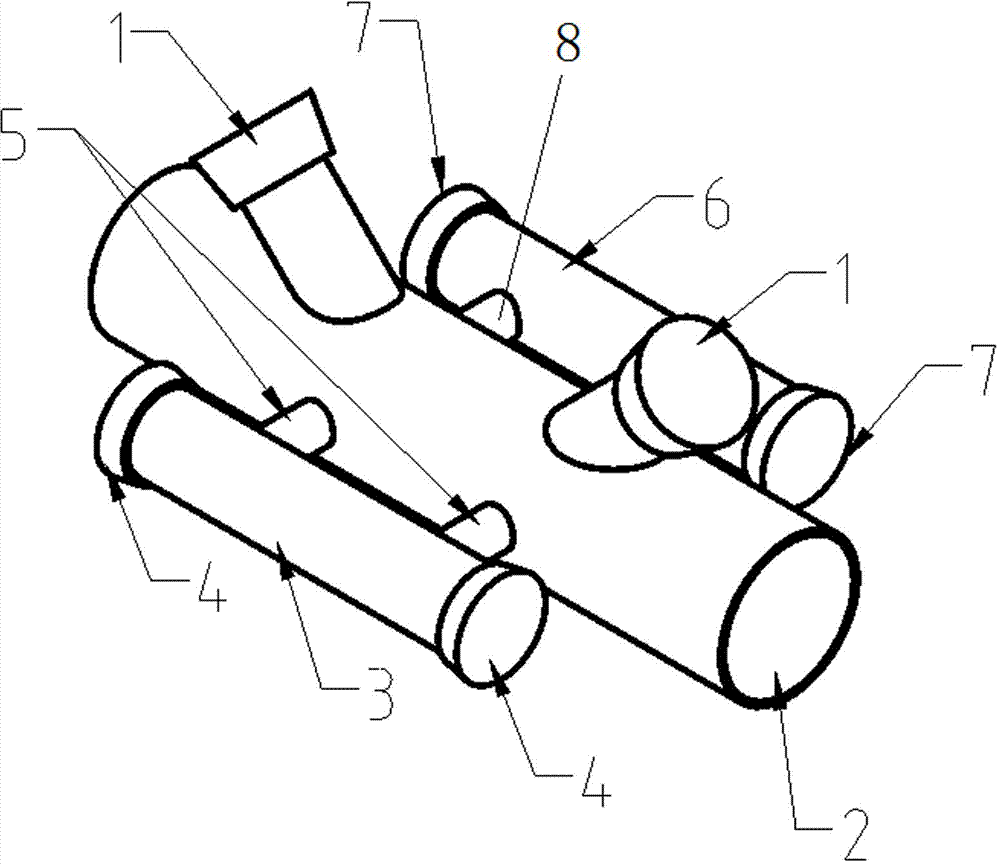
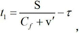
[0026] ① When the gas to be measured flows through the measuring tube, the ultrasonic transducer group arranged on the tube section of the measuring tube measures the downstream time t when the ultrasonic wave propagates downstream in the tube section 1and the countercurrent time t during countercurrent propagation 2 ; When the gas to be measured flows through the section of the measuring tube where the ultrasonic transducer group is arranged, it freely diffuses into the two static tubes connected with the measuring tube. The ultrasonic transducer used to measure the ultrasonic propagation velocity in the tube, according to the layout of the ultrasonic transducer on the static tube, the measured sound path of the ultrasonic wave propagating in the corresponding static tube is obtained, and the length of the two measured so...


PUM


Abstract

The invention discloses a detection method of using ultrasonic waves for flow detection. The detection method includes: an ultrasonic transducer group arranged on a pipe section of a measuring pipe is used for measuring a down-flow time and a reverse-flow time when the ultrasonic waves are in down-flow transmission and reverse-flow transmission in the pipe section respectively; to-be-measured gas is diffused freely to two static speed pipes communicated with the measuring pipe when flowing through the pipe section of the measuring pipe provided with the ultrasonic transducer group, and the corresponding sound path is divided by the practical transmission time of the ultrasonic waves in the corresponding static speed pipe so that the transmission speed in each of the two static speed pipes can be obtained; the transmission speeds of the ultrasonic waves are substituted into an ultrasonic wave transmission speed computational formula so that the ultrasonic wave transmission speeds are obtained; and measured data are substituted into an equation to obtain the flow velocity of to-be-measured fluid in the measuring pipe, so that the flow of the to-be-measured fluid is obtained. The gas in the static speed pipes and the to-be-measured gas in the measuring pipe are guaranteed to be kept in the same state constantly by the aid of the detection method, and measuring accuracy degree is improved.

Description

technical field [0001] The invention belongs to the technical field of gas flow measurement, and in particular relates to a detection method for detecting flow by ultrasonic waves. Background technique [0002] Ultrasonic flow measurement technology is a measurement technology that uses the flow velocity information of the fluid when the ultrasonic signal propagates in the fluid to measure the fluid flow. It has the characteristics of non-contact measurement, high measurement accuracy, wide measurement range, and convenient installation and maintenance. According to the principle of signal detection, the current time difference method ultrasonic flow detection device can be roughly divided into time difference method, frequency difference method, beam shift method, Doppler method and other types, among which the flow detection device based on time difference method is the most widely used. [0003] In fact, because the ultrasonic signal in the fluid medium is compared with t...

Claims


Application Information

Patent Timeline
Patent Type & Authority Patents(China)
IPC IPC(8): G01F1/66G01H5/00
Inventor 王新亚张俊峰李波赵彤凯刘东旭李宏刚
Owner GL TECH CO LTD
Learn More