
Welding fixture

A technology for welding fixtures and top plates, applied in welding equipment, auxiliary welding equipment, welding/cutting auxiliary equipment, etc., can solve problems such as high labor costs, inaccurate solder joints, and increased costs, achieve accurate solder joints, and improve quality The effect of reducing labor costs

Inactive Publication Date: 2015-07-01
KUSN MAIZHI FIXTURE TECH
View PDF7 Cites 0 Cited by
  • Summary
  • Abstract
  • Description
  • Claims
  • Application Information

AI Technical Summary

Problems solved by technology

[0002] In the manufacture of electronic products, it is often necessary to weld the sensor chip and the probe. In the existing technology, manual positioning is used, or even two people cooperate to complete the welding work. Inaccurate solder joints and tilted probes often occur. And other bad phenomena, resulting in follow-up rework, which greatly increases the cost, and requires extremely high labor costs, and the efficiency is extremely low

Method used


Image

  • Welding fixture
  • Welding fixture

Examples


Embodiment Construction

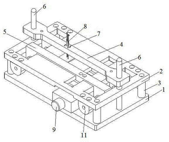
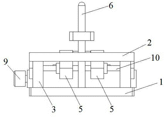
[0013] The present invention will be specifically introduced below in conjunction with the accompanying drawings and specific embodiments.

[0014] see figure 1 and figure 2 , a welding jig of the present invention includes a bottom plate 1 and a top plate 2, and the bottom plate 1 and the top plate 2 are connected by a mounting column 3. It also includes: a needle plate 4, a pair of splints 5, a guide post 6 for its positioning function, and an adjustment mechanism. Wherein, the pinhole 7 for inserting the probe 8 is formed on the needle plate 4 and is installed on the guide post 6. In this way, the guide post 6 can effectively play the role of positioning the needle plate 4 to ensure that it is located at the same position. on flat surface.

[0015] In order to automatically adjust the position of the product to be welded, the adjustment mechanism of the present invention includes: an adjustment knob 9 and a positive and negative screw rod 10 that drives the splint 5 to ...


PUM


Abstract

The invention discloses a welding fixture which comprises a base plate and a top plate, wherein the base plate and the top plate are connected through an installing pillar; and the welding fixture is characterized by also comprising a probe plate, a pair of clamp plates, a guide pillar and an adjusting mechanism, wherein the guide pillar plays a role of positioning, the probe plate is arranged on the guide pillar, pinholes for probes to be inserted into are formed on the probe plate, the adjusting mechanism comprises an adjusting knob and a forward-reverse screw, and the forward-reverse screw drives the clamp plates to move to a middle position. The welding fixture disclosed by the invention has the beneficial effects that the welding fixture can realize fixed-position welding, guarantee the accuracy of welding points, prevent probes from being inclined, and improve the yield of products, meanwhile, the manpower cost is lowered, and the welding efficiency is greatly improved.

Description

technical field [0001] The invention relates to a jig, in particular to a welding jig, which is suitable for welding induction chips in ATE jigs and products of similar design, and belongs to the field of electronic manufacturing. Background technique [0002] In the manufacture of electronic products, it is often necessary to weld the sensor chip and the probe. In the existing technology, manual positioning is used, or even two people cooperate to complete the welding work. Inaccurate solder joints and tilted probes often occur. And other undesirable phenomena, resulting in subsequent rework, greatly increasing the cost, and requires extremely high labor costs, and the efficiency is extremely low. Contents of the invention [0003] In order to solve the deficiencies of the prior art, the object of the present invention is to overcome the deficiencies of the prior art, and provide a welding jig with accurate solder joints, preventing defects and high efficiency. [0004] ...

Claims


Application Information

Patent Timeline
Patent Type & Authority Patents(China)
IPC IPC(8): B23K37/04
Inventor 曹中睿
Owner KUSN MAIZHI FIXTURE TECH
Learn More