
Pipe fitting clamping mechanism

A pipe clamping and pipe clamping technology, which is applied to metal processing equipment, stripping devices, manufacturing tools, etc., can solve problems such as unsafety, low efficiency, and high labor intensity, and achieve high production efficiency, stable operation, and automatic production. Effect

Active Publication Date: 2015-07-22
CHENZHOU ZHIZAO TECH CO LTD
View PDF7 Cites 0 Cited by
  • Summary
  • Abstract
  • Description
  • Claims
  • Application Information

AI Technical Summary

Problems solved by technology

[0002] The production of heat exchangers requires a large number of U-shaped tubes. During the production process, it is necessary to take out the U-shaped tubes that have been bent by the CNC tube bender. In the past, workers took out the U-shaped tubes from the CNC tube bender. This is not only inefficient, unsafe, but also labor-intensive

Method used


Image

  • Pipe fitting clamping mechanism
  • Pipe fitting clamping mechanism
  • Pipe fitting clamping mechanism

Examples


Embodiment

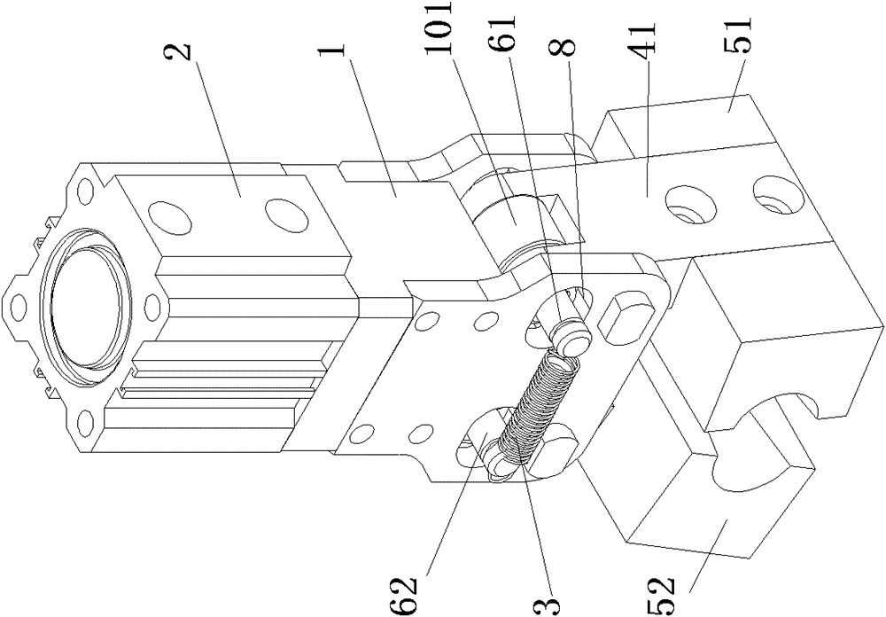
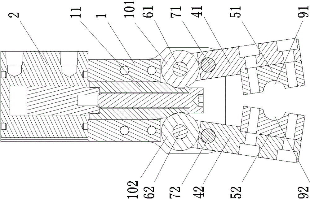
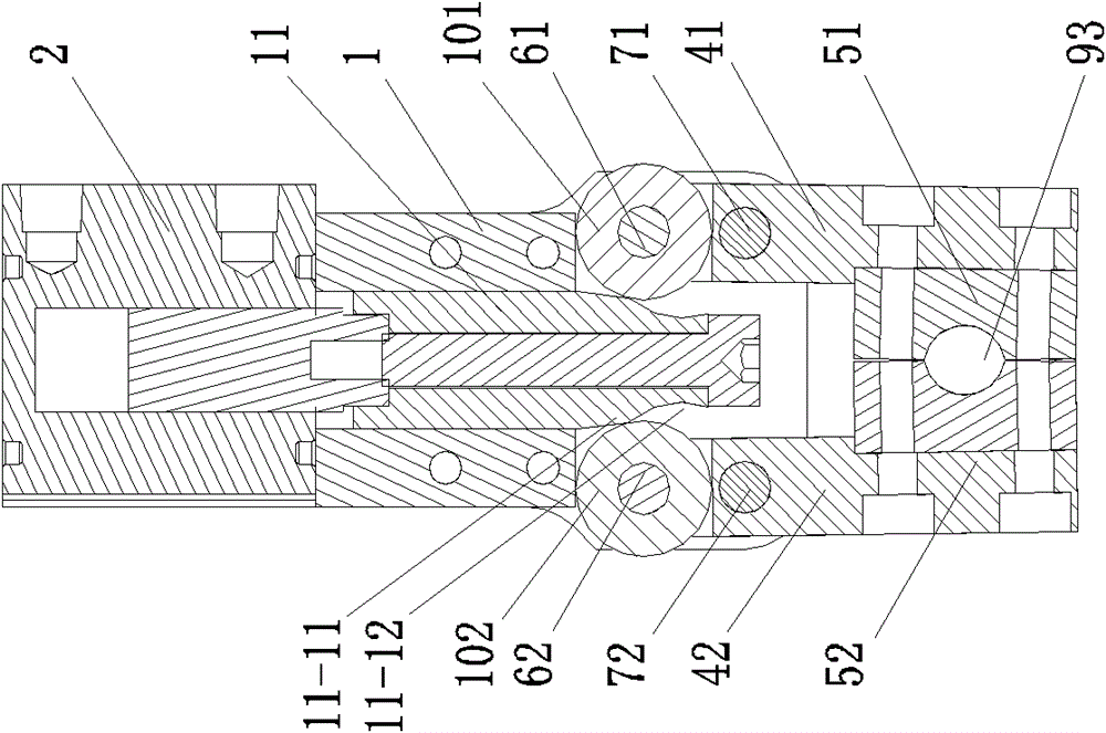
[0015] Embodiment: A clamping mechanism for pipe fittings, including a machine base 1, a push cylinder 2, a return spring 3, a first finger arm 41, a second finger arm 42, a first clamping block 51, a second clamping block 52, a second A pin shaft 61 , a second pin shaft 62 , a first fixed pin shaft 71 and a second fixed pin shaft 72 .

[0016] The two ends of the first finger arm 41 are installed with the first pinch block 51 and the first pin shaft 61 respectively, and the two ends of the second finger arm 42 are respectively installed with the second pinch block 52 and the second pin shaft 62. A chute 8 is provided, and the two ends of the first pin shaft 61 and the second pin shaft 62 protrude from the chute 8 and are connected to the corresponding ends by the return spring 3 , the first pin shaft 61 and the second pin shaft 62 are in the Slide on the chute 8, the first finger arm 41 and the second finger arm 42 are hinged on the base 1 through the first fixed pin shaft 71...

Embodiment approach

[0019] As another embodiment of the present invention, the first roller 101 and the second roller 102 are bearings.


PUM


Abstract

The invention relates to a pipe fitting clamping mechanism. A first pipe clamping block and a first pin shaft are installed at both ends of a first finger arm, a second pipe clamping block and a second pin shaft are installed at both ends of a second finger arm, both ends of the first pin shaft and the second pin shaft extend from sliding chutes and the corresponding end parts are connected by return springs, the first pin shaft and the second pin shaft slip on the sliding chutes, the first finger arm and the second finger arm are respectively hinged on a stand by a first fixing pin shaft and a second fixing pin shaft, the first fixing pin shaft is arranged between the first pipe clamping block and the first pin shaft, and the second fixing pin shaft is arranged between the second pipe clamping block and the second pin shaft. Corresponding idler wheels are arranged on the first pin shaft and the second pin shaft, a push block having two guide faces is installed at the front end of a push shaft of a push cylinder, and a space wide position and a space narrow position are formed on the two guide faces. After the pipe fitting clamping mechanism is adopted, a copper pipe bent by a numerical control pipe bending machine is automatically taken out, the degree of opening is large, and automatic production of the numerical control pipe bending machine is realized. The pipe fitting clamping mechanism is suitable for clamping the copper pipes with different pipe diameters.

Description

(1) Technical field [0001] The invention relates to a pipe clamping mechanism. (2) Background technology [0002] The production of heat exchangers requires a large number of U-shaped tubes. During the production process, it is necessary to take out the U-shaped tubes that have been bent by the CNC tube bender. In the past, workers took out the U-shaped tubes from the CNC tube bender. This is not only inefficient, unsafe, but also labor-intensive. (3) Contents of the invention [0003] In order to solve the above problems, the present invention provides a clamping mechanism for pipe fittings, which can automatically take out the copper pipe bent by the CNC pipe bender, realize the automatic production of the CNC pipe bender, run smoothly, and have high production efficiency. [0004] For this reason, the present invention adopts following scheme to achieve the above object: [0005] A pipe clamping mechanism, comprising a machine base, a push cylinder, a first finger arm...

Claims


Application Information

Patent Timeline
Patent Type & Authority Patents(China)
IPC IPC(8): B21D45/06B21D7/16B21D9/16
Inventor 龙晓斌李建宏
Owner CHENZHOU ZHIZAO TECH CO LTD
Learn More