
Reduced-pressure distillation device

A technology of distillation device and distillation head, which is applied in the directions of laboratory utensils, laboratory containers, chemical instruments and methods, etc., to achieve the effect of simple structure, economical convenience, etc.

Inactive Publication Date: 2013-02-06
UNIV OF JINAN
View PDF5 Cites 6 Cited by
  • Summary
  • Abstract
  • Description
  • Claims
  • Application Information

AI Technical Summary

Problems solved by technology

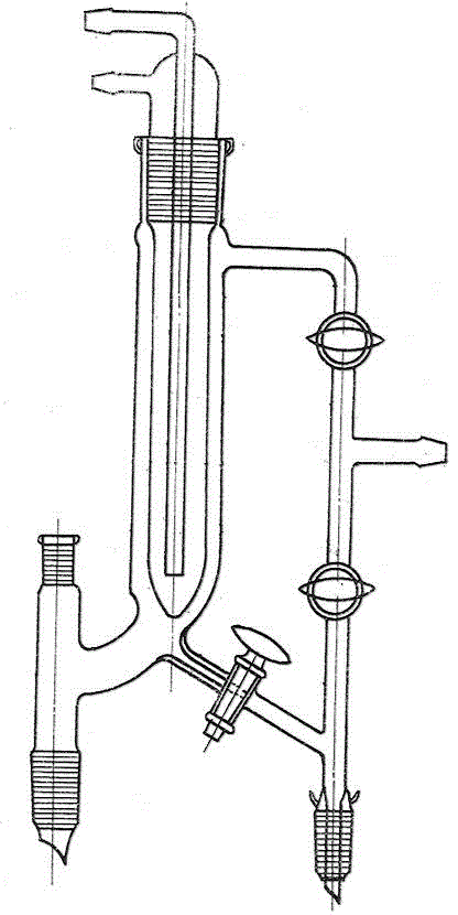
[0002]Figure 1 is a vacuum distillation device. The current vacuum distillation device is a complex monolithic structure with high manufacturing costs. Damage to a certain point will lead to damage to the entire instrument
In addition, during the distillation process, bumping sometimes occurs, causing product contamination and resulting in failure of the distillation operation

Method used


Image

  • Reduced-pressure distillation device
  • Reduced-pressure distillation device
  • Reduced-pressure distillation device

Examples


Embodiment Construction

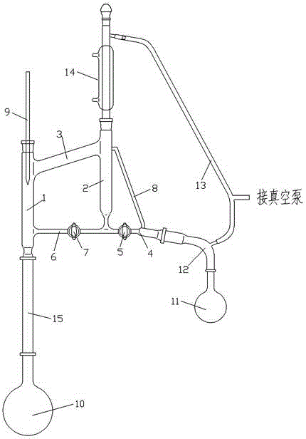
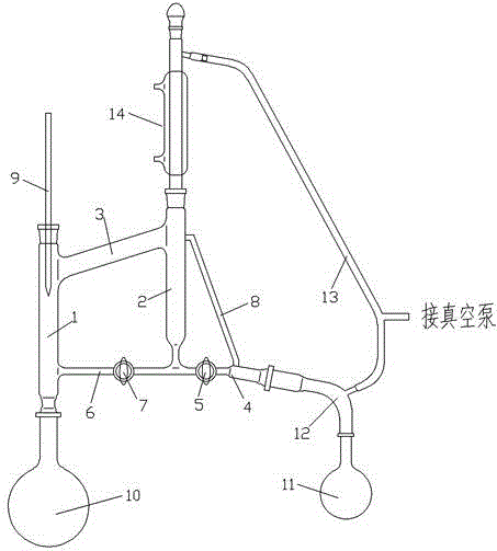
[0021] Such as figure 2 , image 3 with Figure 4 Shown, a kind of vacuum distillation device comprises distillation head, and distillation head comprises steam pipe 1, water distribution pipe 2 and connecting pipe 3, steam pipe has upper port and lower port, water distribution pipe has upper port, the lower end of water distribution pipe and supply The branch pipe 4 with the control valve I5 used for liquid outflow of the water distribution pipe is connected. The outer end of the branch pipe has an outer port. The connecting pipe is used to connect the upper end of the steam pipe and the upper end of the water distribution pipe. A control valve with a control valve connected to the lower end of the water distribution pipe and the steam pipe is arranged below the connecting pipe. Return pipe 6 of II7. A thermometer 9 is inserted into the upper port of the steam pipe, and the lower port of the steam pipe is directly connected to the distillation vessel or communicated with t...


PUM


Abstract

The invention discloses a reduced-pressure distillation device with the advantages of simple structure, economy and convenience. The reduced-pressure distillation device comprises a distillation head; the distillation head comprises a steam pipe, a water distribution pipe and a connecting pipe, wherein the steam pipe is provided with an upper port and a lower port; the water distribution pipe is provided with an upper port; the lower end of the water distribution pipe is communicated with a branch pipe with a control valve I for the outflow of liquid in the water distribution pipe; the outer end of the branch pipe is provided with an outer port; the connecting pipe is used for communicating the upper end of the steam pipe and the upper end of the water distribution pipe; a backflow pipe with a control valve II communicated with the lower end of the water distribution pipe and the steam pipe is arranged below the connecting pipe; a thermometer is inserted at the upper port of the steam pipe; the lower port of the steam pipe is directly communicated with a distillation vessel or is communicated with the distillation vessel through a rectifying column; the upper port of the water distribution pipe is connected with a condenser; the outer port of the branch pipe is connected with a receiving vessel through a vacuum receiving head; both the upper end of the condenser and the vacuum receiving head are connected with an air suction pipe; and the air suction pipe is connected with a vacuum pump.

Description

technical field [0001] The invention relates to a vacuum distillation device. Background technique [0002] figure 1 The vacuum distillation device is a vacuum distillation device. The current vacuum distillation device is a complex monolithic structure with high manufacturing costs, and damage to a certain point will lead to damage to the entire instrument. In addition, during the distillation process, bumping sometimes occurs, causing product contamination and resulting in failure of the distillation operation. Contents of the invention [0003] The technical problem to be solved by the present invention is to provide a vacuum distillation device with simple structure, economy and convenience. [0004] In order to solve the problems of the technologies described above, the technical solution of the present invention is: [0005] A vacuum distillation device, comprising a distillation head, the distillation head includes a steam pipe, a water distribution pipe and...

Claims


Application Information

Patent Timeline
Patent Type & Authority Applications(China)
IPC IPC(8): B01L3/16B01L3/00
Inventor 施强张书香王在震楮国红
Owner UNIV OF JINAN
Learn More