Fuel injection valve
A technology of fuel injection valve and fuel flow path, which is applied to fuel injection devices, charging systems, machines/engines, etc., and can solve problems such as difficulty in manufacturing, difficulty in forming injection holes, and deterioration of manufacturability
- Summary
- Abstract
- Description
- Claims
- Application Information
AI Technical Summary
Problems solved by technology
Method used
Image
Examples
no. 1 approach
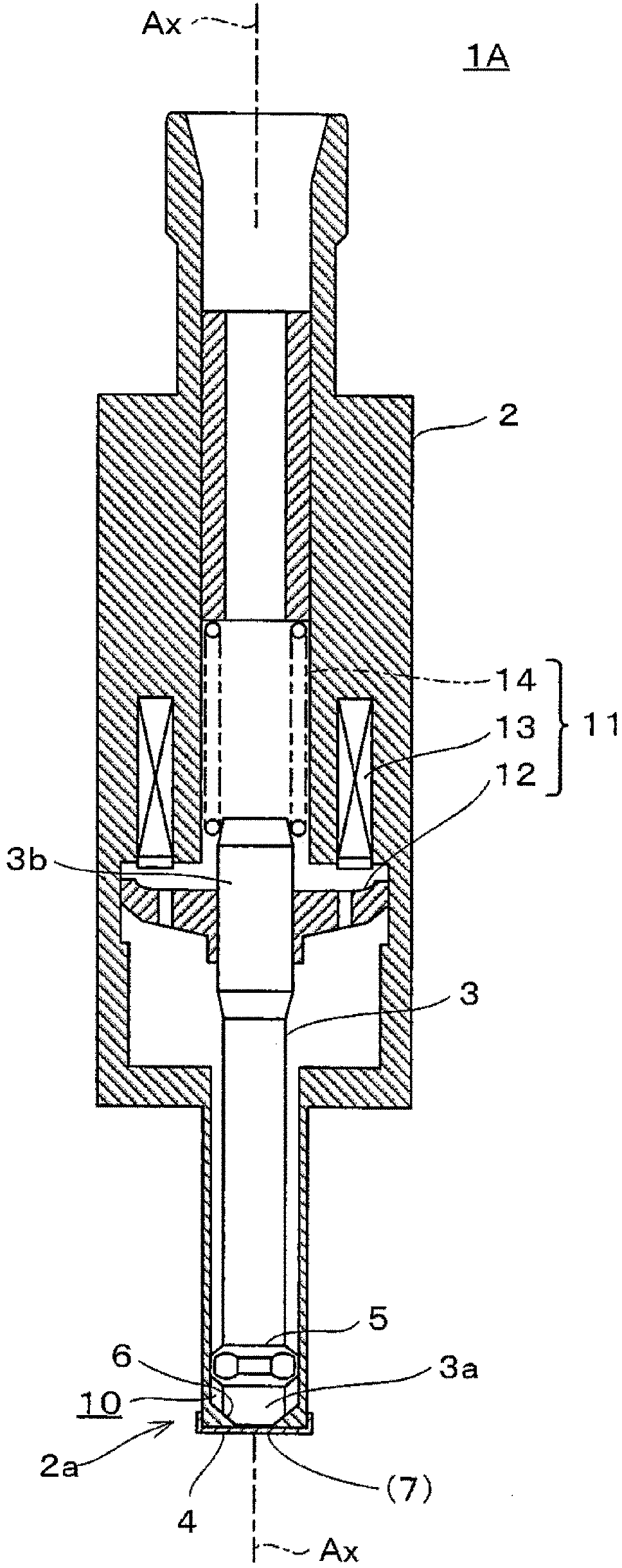
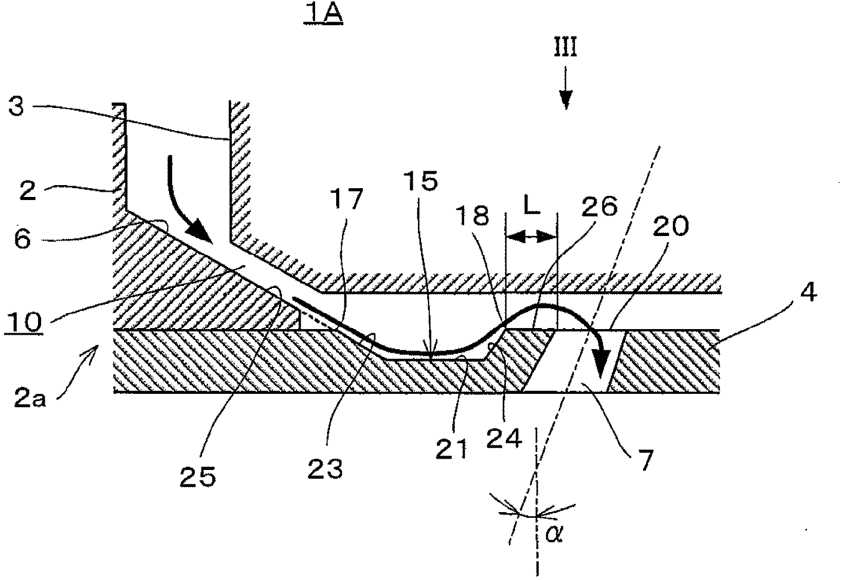
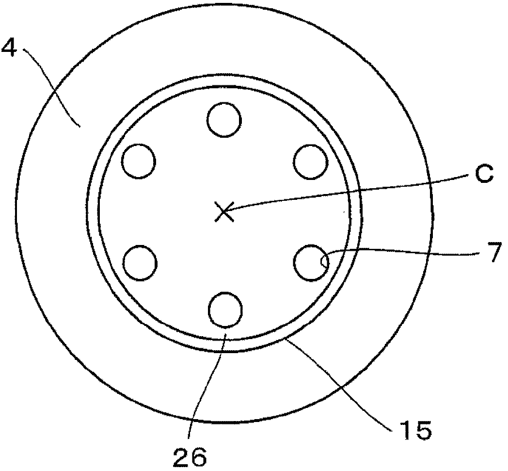
[0050] figure 1 The main structure of the fuel injection valve according to the first embodiment of the present invention is shown. The fuel injection valve 1A is configured as an electromagnetically driven fuel injection valve that can be incorporated into a spark ignition type internal combustion engine and used. The fuel injection valve 1A includes: a valve needle 3 housed in a reciprocating state inside the valve body 2 ; and an orifice plate 4 attached to the front end portion 2 a of the valve body 2 . The needle 3 is supported by the inner peripheral surface of the valve body 2 and the needle guide 5 in a state capable of reciprocating in the direction of the axis Ax. The tip portion 3 a of the needle 3 is configured to be seated on or separated from a valve seat 6 formed on the valve body 2 . A plurality of injection holes 7 are formed in the injection hole plate 4 , and the plurality of injection holes 7 communicate with the inside and outside of the injection hole p...
no. 2 approach
[0058] Second, refer to Figure 4 A second embodiment of the present invention will be described. The second embodiment is the same as the first embodiment except for the shape of the needle. Therefore, the same reference numerals are assigned to the same configurations as those of the first embodiment in the drawings, and description thereof will be omitted. Also, for the basic structure of the second embodiment, refer to figure 1 Wait.
[0059] Figure 4 It is an enlarged cross-sectional view of an orifice plate and its surroundings of the fuel injection valve according to the second embodiment. As shown in the figure, the fuel injection valve 1B includes a needle 30 on which a protrusion 31 is formed facing the recess 15 and protruding toward the side closer to the orifice plate 4 . The protruding amount of the protrusion 31 is adjusted so that when the fuel injection valve 1B is seated, the protrusion 31 is submerged in the recess 15, and when the fuel injection valve...
no. 3 approach
[0062] Second, refer to Figure 5 as well as Figure 6A third embodiment of the present invention will be described. The third embodiment corresponds to an embodiment in which a part of the first embodiment or the second embodiment is modified, and the parts other than the modified points have the same configuration as the above-mentioned embodiment. Therefore, description of the same configuration as that of the first embodiment or the second embodiment is omitted.
[0063] Figure 5 It is an enlarged cross-sectional view of an orifice plate and its surroundings of the fuel injection valve according to the third embodiment. Figure 6 is shown viewed from the direction of arrow VI Figure 5 An explanatory diagram of the state of the orifice plate shown. As shown in these figures, the fuel injection valve 1C includes an orifice plate 32 in which an injection hole 33 is formed, and a groove 34 communicating with the injection hole 33 is formed in the orifice plate 32 . The...
PUM
 Abstract
Description
Claims
Application Information
 - R&D Engineer
- R&D Manager
- IP Professional
- Industry Leading Data Capabilities
- Powerful AI technology
- Patent DNA Extraction
Browse by: Latest US Patents, China's latest patents, Technical Efficacy Thesaurus, Application Domain, Technology Topic, Popular Technical Reports.
© 2024 PatSnap. All rights reserved.Legal|Privacy policy|Modern Slavery Act Transparency Statement|Sitemap|About US| Contact US: help@patsnap.com


