
Method and device for measuring flow of gate

A technology of flow measuring device and gate, applied in measuring device, measuring flow/mass flow, liquid/fluid solid measurement, etc., can solve the problems of limiting the application of gate water measurement, low flow measurement accuracy, and no solution, etc. Low-cost, high-precision flow calculation, simple structure

Inactive Publication Date: 2013-01-30
唐山现代工控技术有限公司
View PDF5 Cites 10 Cited by
  • Summary
  • Abstract
  • Description
  • Claims
  • Application Information

AI Technical Summary

Problems solved by technology

[0002] At present, the existing water conservancy sluice flow measurement methods use different calculation formulas according to four different flow states: namely: submerged flow without sluices, free flow without sluices, submerged flow with sluices, and free flow with sluices, using these four flow state formulas to calculate The flow through the gate has the following defects: ① It is necessary to install a gate level sensor and a water level sensor in front of the gate and behind the gate, which is expensive and difficult to maintain; ② The flow measurement accuracy is low, and the general error is more than 15%.
The above-mentioned defects have plagued industry personnel for a long time, but there has been no better solution for many years, which limits the application of gate water measurement to a certain extent

Method used


Image

  • Method and device for measuring flow of gate
  • Method and device for measuring flow of gate
  • Method and device for measuring flow of gate

Examples


Embodiment Construction

[0025] The present invention will be further described through the embodiments below in conjunction with the accompanying drawings.

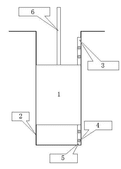
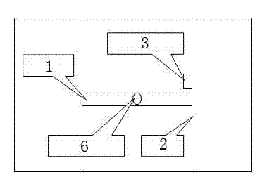
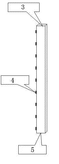
[0026] A flow measuring device for a gate, comprising a casing 3, a plurality of flow velocity sensors 4 and a water level sensor 5, the casing is in the shape of a strip, and is vertically arranged on the side wall of the gate 2, and a plurality of flow velocity sensors are arranged at intervals on the casing, The arrangement direction of the plurality of flow rate sensors is perpendicular to the ground, and the water level sensor is arranged at the bottom of the casing.

[0027] The intervals between the plurality of flow rate sensors are equal or unequal. The bottom of the shell is matched with a steady flow device. The flow velocity and water level signals output by the flow velocity sensor and the water level sensor are connected to the intelligent circuit for processing.

[0028] A gate flow measurement method, the above-mentioned gate f...


PUM


Abstract

The invention relates to a method and a device for measuring flow of a gate, belonging to the technical field of flow measurement and data remote transmission of water conservancy gates. The technical scheme provided by the invention is as follows: a velocity field with non-uniform gateways is horizontally partitioned by utilizing a horizontal partitioning method; the relationship between average flow velocity and the flow velocity of a measurement point of a horizontal flow layer is found out by utilizing symmetrical characteristic of the velocity field after horizontally partitioning; the horizontal partition flow is obtained by utilizing a flow velocity-area method; the total number of the practical horizontal partition layers is obtained by utilizing a water-level sensor; and the horizontal partition flows are added to obtain flow passing through the gate. All are linked with one another; none is dispensable; the method and the device have the advantages of smart conception, rigorous design, simple structure, low cost, high measurement precision, simplicity and practicability; the device is capable of completing measurement of average flow of various flow layers; the flow can be precisely calculated by utilizing the flow velocity-area method; data acquisition, data calculation, data recording and data transmission can be completed through an intelligent circuit; the maintenance amount is low; continuous online measurement is realized; the flow is calculated in high precision; and the method and the method are convenient for administrative departments to manage.

Description

technical field [0001] The invention relates to a gate flow measurement method and device, and belongs to the technical field of water conservancy gate flow measurement and data remote transmission. Background technique [0002] At present, the existing water conservancy sluice flow measurement methods use different calculation formulas according to four different flow states: namely: submerged flow without sluices, free flow without sluices, submerged flow with sluices, and free flow with sluices, using these four flow state formulas to calculate The flow through the gate has the following defects: ① It is necessary to install a gate level sensor and a water level sensor in front of the gate and behind the gate, which is expensive and difficult to maintain; ② The flow measurement accuracy is low, and the general error is more than 15%. The above-mentioned defects have plagued industry personnel for a long time, but there has been no better solution for many years, which lim...

Claims


Application Information

Patent Timeline
Patent Type & Authority Applications(China)
IPC IPC(8): G01F1/00
Inventor 张喜马月坤苏立业许卓宁于树利刘峰
Owner 唐山现代工控技术有限公司
Learn More