
Reluctance type inclination angle sensor

An inclination sensor, magnetoresistive technology, applied in instruments, measuring inclination, using electromagnetic means, etc., can solve the problems of increasing the cost of feedback system, expensive sensor, unfavorable application, etc., to achieve high dynamic accuracy, large measurement range, simple structure

Active Publication Date: 2013-01-30
BEIJING UNIV OF POSTS & TELECOMM
View PDF5 Cites 5 Cited by
  • Summary
  • Abstract
  • Description
  • Claims
  • Application Information

AI Technical Summary

Problems solved by technology

[0011] The measurement of the magnetoresistive principle sensor is affected by the magnetic field of the surrounding environment on the one hand (such as tall buildings, iron mines, power plants, high-voltage substation equipment, etc., and even steel objects close to the sensor), on the other hand, although the existing magnetic The resistance principle sensor has a static magnetic field correction function, but it does not have a correction function for a dynamic magnetic field, so it is not suitable for inclination measurement in a dynamic system
[0012] The high-end gyroscope can output three rotation angles, angular velocity and angular acceleration of the Euler angle in space, and translational velocity and translational acceleration in three directions. Although the sensor of the high-end gyroscope can be applied to the inclination measurement in the dynamic system, This type of sensor is relatively expensive, which will greatly increase the cost of the feedback system, which is not conducive to wide application

Method used


Image

  • Reluctance type inclination angle sensor
  • Reluctance type inclination angle sensor
  • Reluctance type inclination angle sensor

Examples


Embodiment Construction

[0036] The technical solutions in the embodiments of the present invention will be clearly and completely described below in conjunction with the accompanying drawings in the embodiments of the present invention. Apparently, the described embodiments are only some, not all, embodiments of the present invention. Based on the embodiments of the present invention, all other embodiments obtained by persons of ordinary skill in the art without creative efforts fall within the protection scope of the present invention.

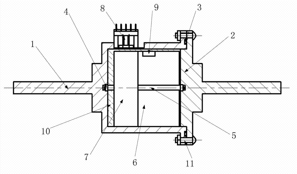
[0037] Please refer to figure 1 as shown, figure 1 It is a schematic diagram of the overall composition and structure of an inclination sensor provided by the present invention.

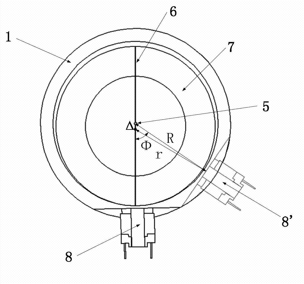
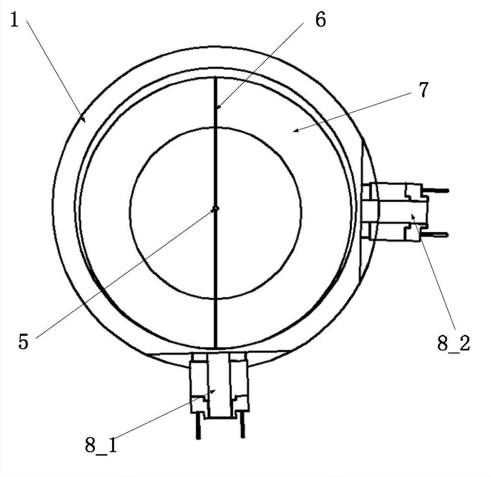
[0038] An inclination sensor provided by the present invention includes: a cylinder body 1, an end cover 2, a connector 4, a mandrel 5, a fixing plate 6, an annular soft magnet 7, an E-type soft magnet coil 8, and a detection circuit;

[0039]Wherein, there is a through groove 51 in the ...


PUM


Abstract

The invention provides a reluctance type inclination angle sensor. The reluctance type inclination angle sensor comprises a cylindrical body, an end cover, a connecting piece and a mandrel, a fixed plate, an annular soft magnet, E-type soft magnet coils and a detection circuit, wherein a through groove is formed in the center of the mandrel; the fixed plate is connected with the mandrel through the through groove; the fixed plate and the mandrel penetrate through and are arranged in the annular soft magnet; two side edges of the fixed plate are fixedly connected with the inner side surface of the annular soft magnet; the connecting piece is positioned on the cylindrical body and / or the end cover and is matched with and connected with two ends of the mandrel; the E-type soft magnet coils are arranged on the outer side surface of the cylindrical body; the cylindrical body is in sealed connection with the end cover to form a closed cavity; the annular soft magnet and the cylindrical body are eccentrically fixed through the fixed plate; and the detection circuit is connected with the E-type soft magnet coils and is used for detecting an oscillation frequency value, wherein an inclination angle is obtained by mapping the oscillation frequency value.

Description

technical field [0001] The invention relates to the field of data information detection, in particular to a magnetoresistive inclination sensor. Background technique [0002] A sensor is a detection device that can feel the measured information, and can convert the detected information into electrical signals or other required forms of information output according to certain rules, so as to meet the needs of information transmission, processing, storage, display, recording and control requirements. It is the first link to realize automatic detection and automatic control. [0003] As a kind of sensor, the inclination sensor is an instrument made on the basis of Newton's second law and used to measure the angle of an object relative to the horizontal plane. That is, the inclination sensor can be used to measure the change in inclination relative to the horizontal plane. [0004] Inclination sensors are widely used in various applications for measuring angles. For example,...

Claims


Application Information

Patent Timeline
Patent Type & Authority Applications(China)
IPC IPC(8): G01C9/00G01B7/30
Inventor 郭磊廖启征孟祥珺卢光磊石俊峥
Owner BEIJING UNIV OF POSTS & TELECOMM
Learn More