
Low-range circulating fluidized bed water boiler for combusting inferior fuel and combustion method thereof

A technology of circulating fluidized bed and hot water boiler, which is applied in the direction of fluidized bed combustion equipment, combustion method, and fuel burned in a molten state, can solve the problem of inability to reduce the carbon content of fly ash, low boiler thermal efficiency, water wall wear, etc. problems, to achieve the effects of improving combustion efficiency and thermal efficiency, reducing wear and reducing carbon content

Active Publication Date: 2015-03-11
哈尔滨红旗锅炉有限公司
View PDF4 Cites 11 Cited by
  • Summary
  • Abstract
  • Description
  • Claims
  • Application Information

AI Technical Summary

Problems solved by technology

[0003] The present invention solves the problem that the existing layer-fired hot water boilers can only burn high-quality coal, while conventional circulating fluidized bed boilers burn bad coal when the water wall is severely worn, and the existing hot water boilers cannot reduce the carbon content of the fly ash and the thermal efficiency of the boiler is relatively low. Therefore, a low-rate circulating fluidized bed hot water boiler and its combustion method for burning inferior fuels are proposed

Method used


Image

  • Low-range circulating fluidized bed water boiler for combusting inferior fuel and combustion method thereof
  • Low-range circulating fluidized bed water boiler for combusting inferior fuel and combustion method thereof
  • Low-range circulating fluidized bed water boiler for combusting inferior fuel and combustion method thereof

Examples


specific Embodiment approach 1

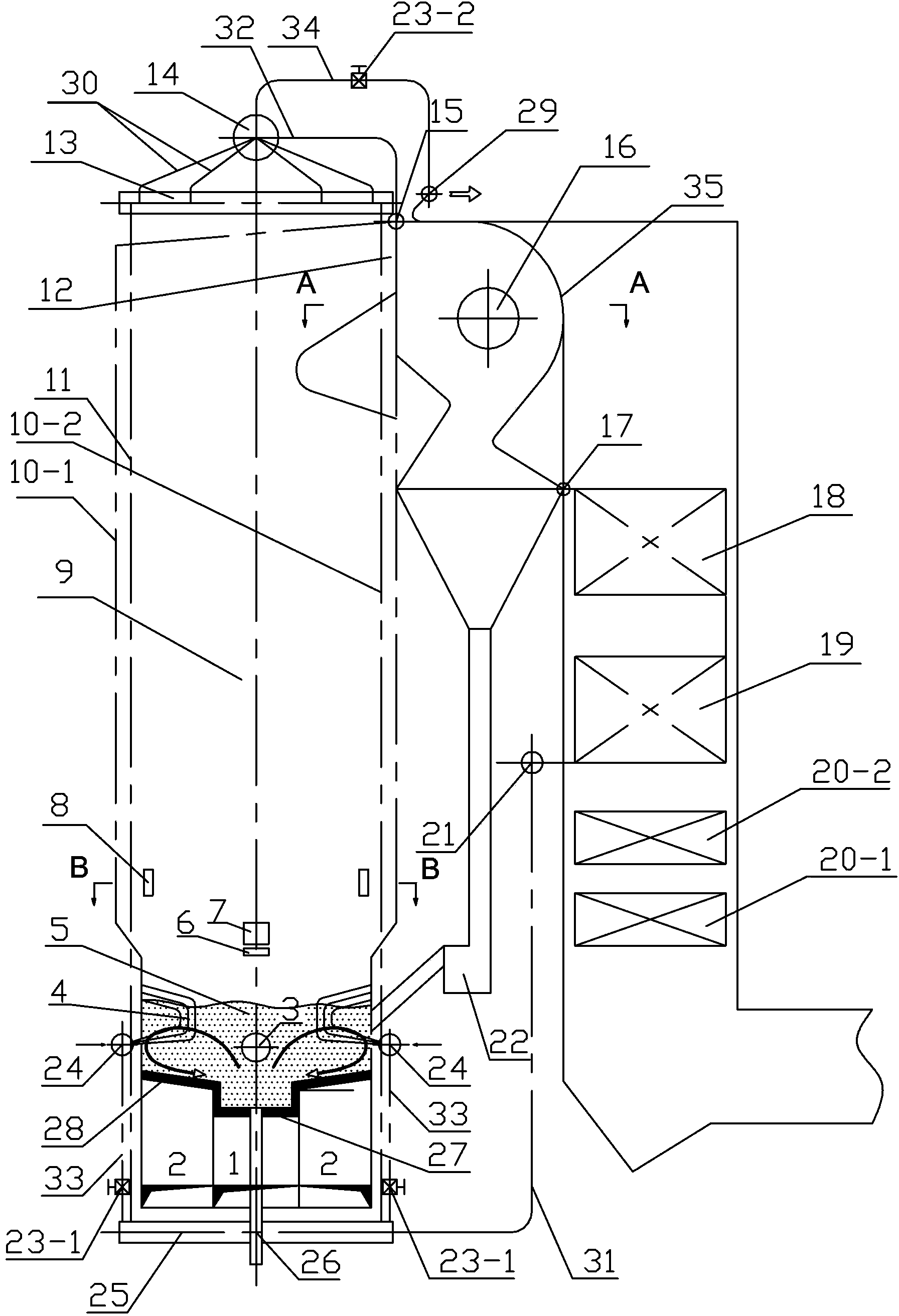
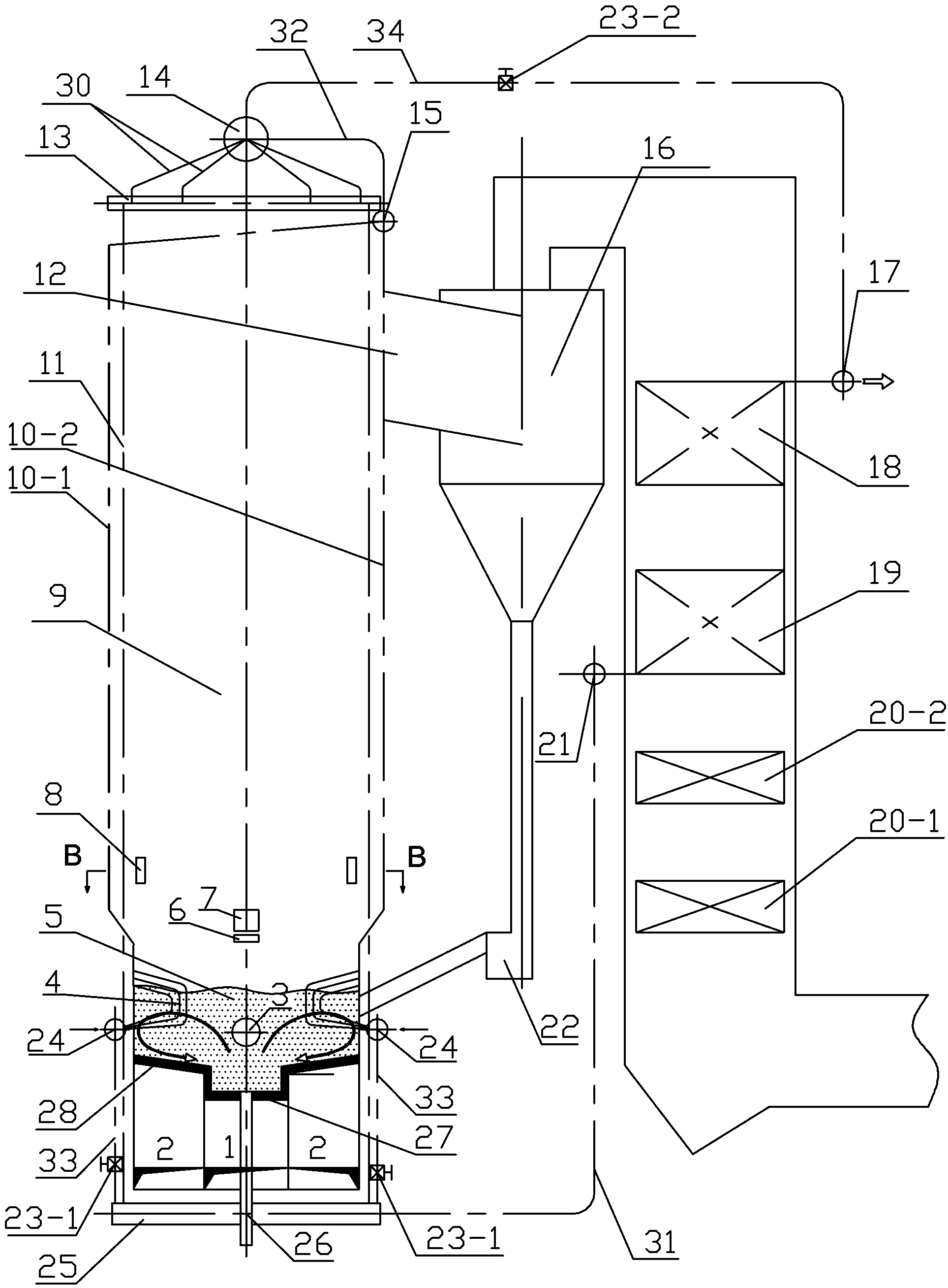
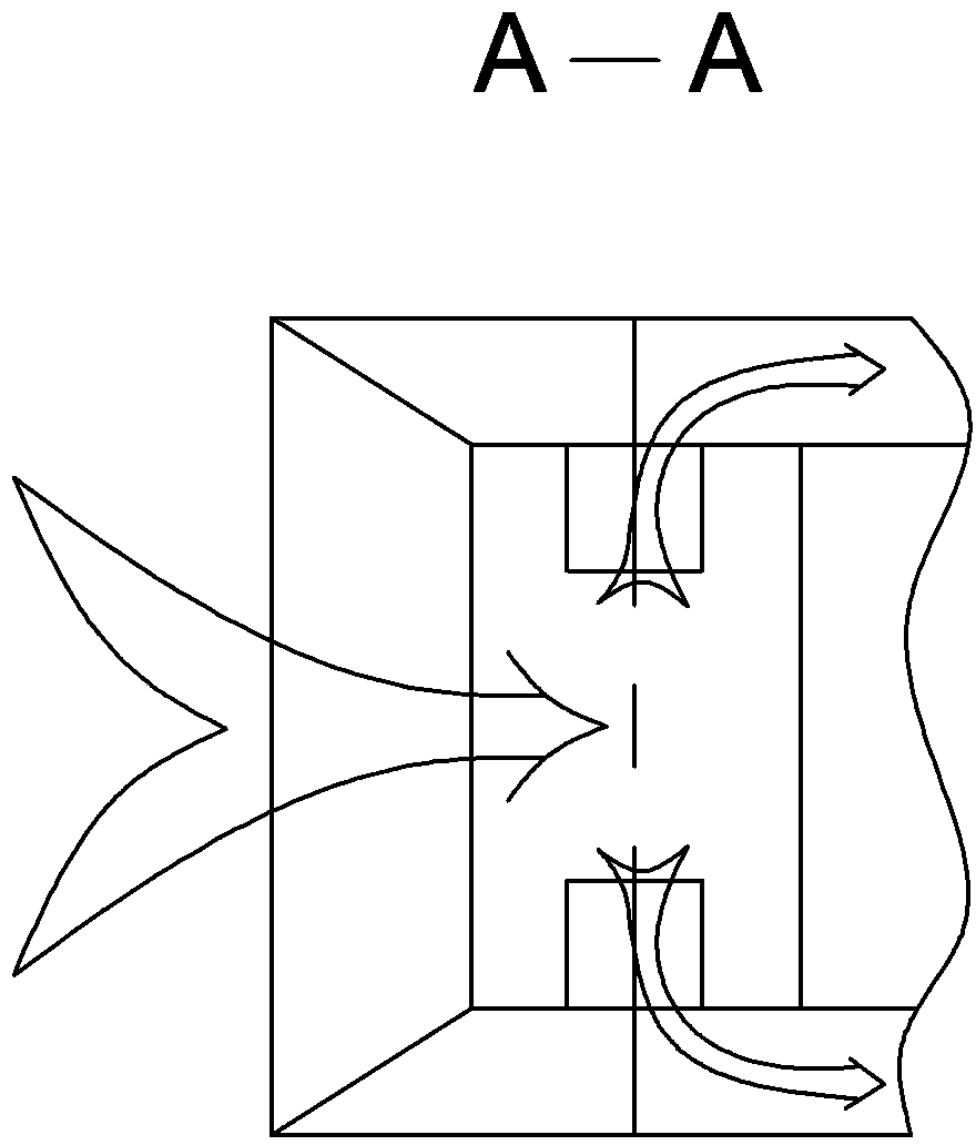
[0014] Specific implementation mode one: combine figure 1 and image 3 Describe this embodiment. A low-rate circulating fluidized bed hot water boiler that burns low-quality fuels in this embodiment includes a high-speed bed air chamber 1, two low-speed bed air chambers 2, a furnace door 3, buried pipes 4, and a dense phase area. 5. Coal sowing air 6, coal supply port 7, rotating air secondary air port 8, dilute phase area 9, front wall water cooling wall 10-1, rear wall water cooling wall 10-2, two side wall water cooling walls 11, furnace outlet 12. Header 13 on both sides of the water-cooled wall, drum 14, collection box 15 on the front and rear water-cooled walls, cyclone separator 16, high-temperature economizer outlet header 17, high-temperature economizer 18, and low-temperature economizer 19 , primary air air preheater 20-1, secondary air air preheater 20-2, low-temperature economizer inlet header 21, feeder 22, front and rear wall buried pipe lower header 24, water-c...

specific Embodiment approach 2

[0017] Specific implementation mode two: combination figure 1 Describe this embodiment, the fourth connecting pipe between the lower headers 24 of the front and rear wall buried pipes and the lower headers 25 of the water-cooled walls on both sides of a low-rate circulating fluidized bed hot water boiler that burns inferior fuels in this embodiment 33 is provided with a first valve 23-1, and the fifth connecting pipe 34 between the cyclone separator outlet header 29 and the drum 14 is provided with a second valve 23-2. The technical effect of this embodiment is: when sudden power failure occurs, the front wall water cooling wall 10-1, the rear wall water cooling wall 10-2, the two side wall water cooling walls 11 and the drum 14 in the furnace body, and the drum 14 and the The heated surface of the tail forms a natural circulation without water hammer. Other components and connections are the same as those in the first embodiment.

specific Embodiment approach 3

[0018] Specific implementation mode three: combination figure 1 Describe this embodiment. The cyclone separator 16 of a low-rate circulating fluidized bed hot water boiler that burns low-quality fuel in this embodiment is a water-cooled horizontal cyclone separator with an acceleration section, and the outlet header 29 of the cyclone separator is a water-cooled horizontal cyclone separator with an acceleration section. The outlet header of the section water-cooled horizontal cyclone separator. The technical effects of this embodiment are: 1, because the separator is water-cooled, coking will not occur in the separator due to reburning; 2, the refractory material covered on the surface of the separator is thinner (about 100 mm), and the start-up time is relatively short ( 3-4 hours), saving fuel for the furnace; 3. According to needs, multiple separators can be evenly arranged at the furnace outlet, and the flue gas flow field is uniform; 4. The horizontal water-cooled cyclone ...


PUM


Abstract

The invention relates to a low-range circulating fluidized bed water boiler for combusting inferior fuel and a combustion method of the low-range circulating fluidized bed water boiler, and particularly relates to a circulating fluidized bed water boiler and a combustion method of the low-range circulating fluidized bed water boiler. The invention aims to solve the problem that the conventional grate firing water boiler can only combust high-quality coal and the water wall of the conventional circulating fluidized bed water boiler is seriously abraded when inferior fuel is combusted. Multiple buried pipes are uniformly arranged on both sides in a low-speed bed in a dense-phase area on the lower part of the boiler body; both sides of a high-speed bed air chamber are respectively provided with a low-speed bed air chamber; an intermediate wind-distribution plate is arranged at the upper part of the high-speed bed air chamber; the upper part of each low-speed bed air chamber is respectively provided with a side wind-distribution plate; a two-side wall water-cooling wall upper header is arranged at the upper end of the boiler body; a two-side wall water-cooling wall lower header is arranged at the lower end of the boiler body; a boiler barrel is arranged on the upper part of the two-side wall water-cooling wall upper header; and the two-side wall water-cooling upper header is communicated with the boiler barrel through a first connecting pipe. The low-range circulating fluidized bed water boiler for combusting inferior fuel is applied to the fields of utility boilers, industrial boilers and waste disposal utilization.

Description

technical field [0001] The invention relates to a circulating fluidized bed hot water boiler and a combustion method thereof, in particular to a low-rate circulating fluidized bed hot water boiler burning low-quality fuel and a combustion method thereof. Background technique [0002] The furnace types of hot water boilers include layer-fired furnaces (including chain furnaces and reciprocating grate furnaces) and circulating fluidized bed boilers. Existing chain hot water boilers can generally only burn high-quality fuel above Class II bituminous coal; existing large-scale reciprocating grate hot water boilers can generally burn about 3500Kcal / kg lignite or high-quality bituminous coal above Class II bituminous coal. Existing circulating fluidized bed hot water boilers generally require the calorific value of coal to be above 2800Kcal / kg, and the water-cooled wall of the furnace is severely worn when burning low-quality coal, which generally only lasts for 6 to 12 months. I...

Claims


Application Information

Patent Timeline
Patent Type & Authority Patents(China)
IPC IPC(8): F24H1/44F24H9/20F23C10/00F23C10/18F23C10/20F23L15/00
CPCY02E20/34
Inventor 别如山朱少飞宋兴飞纪晓瑜黄兵陈佩刘茜茜
Owner 哈尔滨红旗锅炉有限公司
Learn More