
Balance pump

A technology for balancing pumps and pump bodies, which is applied to pump components, variable displacement pump components, components of pumping devices for elastic fluids, etc. Problems such as limited blocking effect of the valve

Active Publication Date: 2013-01-30
贝恩医疗设备(广州)有限公司
View PDF8 Cites 5 Cited by
  • Summary
  • Abstract
  • Description
  • Claims
  • Application Information

AI Technical Summary

Problems solved by technology

The balance pump in the prior art is usually provided with a one-way valve at the joint to allow the liquid to flow in one direction. However, when the balance pump operates, the pressure at the outlet of the balance pump (that is, at the joint) changes greatly, resulting in the failure of the one-way valve. The blocking effect is limited, and the backflow of liquid cannot be effectively prevented, so that the flow balance cannot be precisely controlled

Method used


Image

  • Balance pump
  • Balance pump
  • Balance pump

Examples


Embodiment 1

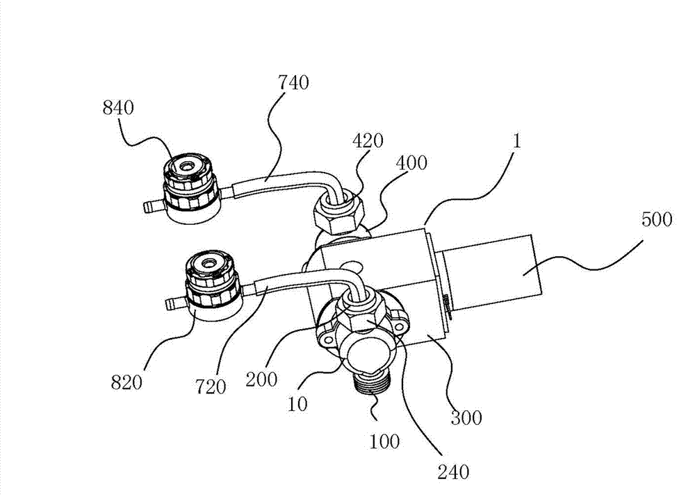
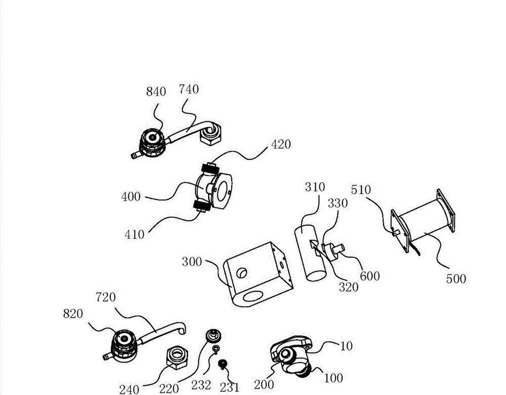
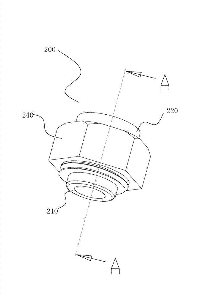
[0063] A balanced pump such as Figure 1 to Figure 5As shown, a pump body 1 , a driving motor 500 , a transmission device, a first connecting pipe 720 , a second connecting pipe 740 , a first back pressure valve 820 and a second back pressure valve 840 are provided. In order to achieve better positioning, a frame can also be provided, and the motor 500 can be installed on the frame.

[0064] The pump body 1 is provided with a first end 10 , a pump chamber 300 , a ceramic piston 310 and a second end 400 .

[0065] The ceramic piston 310 is gap-fitted and movably arranged in the pump chamber 300 . The ceramic piston 310 is connected to one end of the transmission device, and the other end of the transmission device is connected to the motor shaft 510 of the motor 500 .

[0066] Specifically, the transmission device is set as an eccentric shaft 600, the ceramic piston 310 is provided with a groove 320, and a slider 330 is installed in the groove 320, one end of the eccentric sha...

Embodiment 2

[0100] A balance pump, the other structures are the same as in Embodiment 1, the difference is that: the first end 10 and the second end 400 have the same specifications and dimensions, the first joint 100, the second joint 200, the third joint 410, the fourth joint The 420 has the same specification dimensions.

[0101] Since the first end 10 and the second end 400 of the balance pump have the same specification and size, and the first joint 100 , the second joint 200 , the third joint 410 and the fourth joint 420 with the same specification are used.

[0102] Therefore, in one cycle, the amount of waste liquid F4 that flows out from the outlet of the fourth joint 420 is equal to the amount of fresh liquid X2 that flows out from the outlet of the second joint 200, thereby ensuring that the fresh liquid in and out of the dialyzer is equal to the amount of fresh liquid that flows out of the dialyzer in one cycle. Equal amount of waste liquid.

Embodiment 3

[0104] Other structures of a balanced pump are the same as those in Embodiment 1 or 2, except that the pump body adopts a diaphragm type balanced pump. The structure of the diaphragm balance pump is common knowledge in the art, and will not be repeated here.

[0105] Since the output end of the balance pump is provided with a back pressure valve, the conduction pressure of the one-way valve is raised, and the backflow phenomenon of the one-way valve caused by the pressure change at the outlet of the balance pump is avoided, so that the flow balance can be precisely controlled. And the setting of the back pressure valve, although the outlet pressure of the balance pump exists, can avoid the large pulsation phenomenon when the liquid flows in the whole device, and the liquid flows through the dialyzer more gently, thereby ensuring the effect of dialysis treatment.


PUM


Abstract

The invention discloses a balance pump which is provided with a pump body, a drive motor, a transmission device, a first connection pipe, a second connection pipe, a first back pressure valve and a second back pressure valve, wherein the pump body is provided with a first end, a pump cavity, a ceramic piston and a second end; the first end and the second end are arranged at the two ends of the pump cavity and communicated with the pump cavity; the ceramic piston is in clearance assembly and is movably arranged in the pump cavity; the ceramic piston is connected with one end of the transmission device, and the other end of the transmission device is connected with a motor shaft of the motor; the first end is provided with a first joint and a second joint; the second end is provided with a third joint and a fourth joint; a one-way valve is arranged in each joint; one end of the first connection pipe is connected with the second joint, and the other end of the first connection pipe is connected with the first back pressure valve; and one end of the second connection pipe is connected with the fourth joint, and the other end of the second connection pipe is connected with the second back pressure valve. The balance pump can accurately control the flow balance, and also provides power to the liquid flow.

Description

technical field [0001] The invention relates to the technical field of medical equipment, in particular to a balance pump for a dialysis machine. Background technique [0002] Hemodialysis is one of the most effective ways to treat various acute and chronic renal failure diseases. Through hemodialysis, the life span of patients can be appropriately prolonged. Hemodialysis technology has been relatively mature, and further improving the quality of hemodialysis has become one of the development directions for the treatment of patients with renal failure. [0003] Hemodialysis is usually carried out by using a dialysis machine, a dialyzer and corresponding connecting pipelines, and arterial blood and dialysate in the dialyzer enter the dialyzer respectively. The flow direction of the dialysate in the dialyzer is opposite to the flow direction of the blood. Under the action of the osmotic pressure and the pressure of the dialysate, the blood and the dialysate exchange the toxin...

Claims


Application Information

Patent Timeline
IPC IPC(8): F04B53/16F04B53/10A61M1/14
Inventor 蒋顺忠范江红夏武兵
Owner 贝恩医疗设备(广州)有限公司
Learn More