
Material conveyer device used in press machine

A material conveying device and press technology, applied in the direction of feeding device, positioning device, storage device, etc., can solve the problems of difficult mechanical action, long time consumption, difficult identification of input data, etc., to improve reliability and efficient confirmation. and verification work, the effect of reducing the load

Inactive Publication Date: 2013-01-30
欧立机电株式会社
View PDF9 Cites 1 Cited by
  • Summary
  • Abstract
  • Description
  • Claims
  • Application Information

AI Technical Summary

Problems solved by technology

[0005] However, as disclosed in Reference 2, as a function of a device for confirming data related to the input product and mold, it only has the function of correctly displaying the input value itself.
In addition, it is difficult to visualize the shape of the product processed from this numerical value and to predict the actual mechanical operation.
Therefore, when there is an error in the input data and no error is found and trial processing is carried out with the actual machine, the countermeasures when processing failure occurs are complicated and often take a long time.
It is difficult to identify whether the input data is bad or the mold and conveying device are bad

Method used


Image

  • Material conveyer device used in press machine
  • Material conveyer device used in press machine
  • Material conveyer device used in press machine

Examples


Embodiment 1

[0049] Next, Embodiment 1 of the present invention will be described according to the accompanying drawings.

[0050] A. The structure of the press:

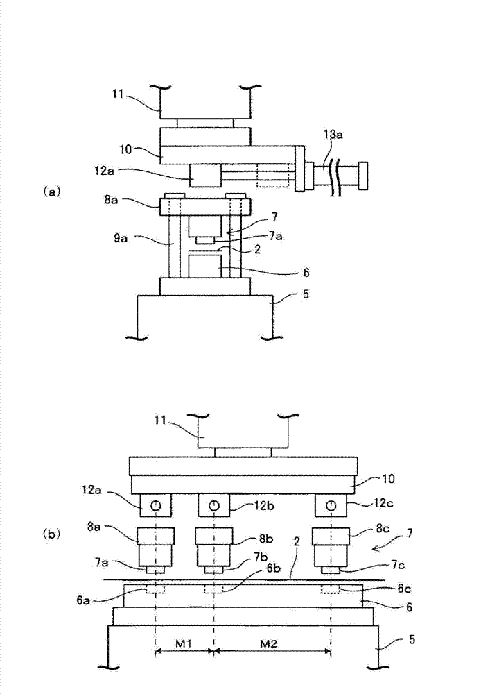
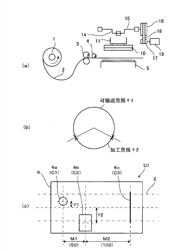
[0051] First, an example of a press machine will be described. figure 2 (a) is a side view of the main part of the press, (b) is a front view of the main part of the press, image 3 (a) is an overall structural diagram of the press.

[0052] Such as image 3 As shown in (a), according to the specified unwinding speed (linear speed) VL, the coil 2 (material) unwound from the unwinding roller 1 is output by a pair of feeding rollers 3, and is introduced into the processing machine after passing through the measuring roller 4. on the base 5 of the table. In addition, if figure 2 As shown, a lower mold 6 is fixed on the base 5 , and an upper mold 7 is disposed above the lower mold 6 . The upper die 7 is divided into a plurality of processing dies 7a, 7b, and 7c in the conveying direction of the coil 2. As shown in FIG. In a...


PUM


Abstract

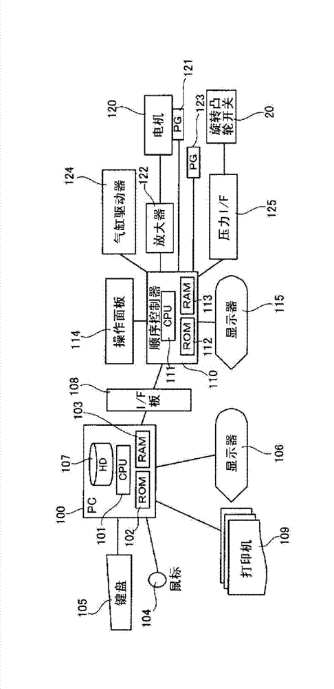
The invention provides a material conveyer device used in a press machine. The material conveyer device comprises a mold data storage unit (a hard disk device (107), etc.), a product data storage unit, and a control unit (a computer (100)). The mold data storage unit is stored with mold data including types of processing molds and arrangement of the processing molds, and configuration space information of the processing molds input by an input unit (a keyboard (105), a mouse (104)). The product data storage unit is stored with product data including product processing spaces and product processing mold information input by the input unit. The control unit portrays an image from which a processing result of the product can be seen according to the mold data and the product data, and has a function of displaying the image on a display unit (a display (106)). According to the material conveyer device, processing operation can be confirmed and verified before actual processing.

Description

technical field [0001] The invention relates to a material conveying device for a press. Background technique [0002] Reference 1 discloses a conveying device for a press machine using a plurality of dies, which does not require troublesome data setting while specifying the conveying length and functioning dies while performing processing. Certainly. [0003] Patent Document 1: Japanese Patent Application Laid-Open No. 9-201632 [0004] Patent Document 2: Japanese National Publication No. 2004-521750 [0005] However, as disclosed in Patent Document 2, as a function of a device for confirming input data related to a product and a mold, it only has a function of correctly displaying the input numerical value itself. In addition, it is difficult to visualize the shape of a product processed from this numerical value and to predict the actual mechanical operation. Therefore, when there is an error in the input data and no error is found and trial processing is performed wi...

Claims


Application Information

Patent Timeline
Patent Type & Authority Applications(China)
IPC IPC(8): B21D43/00
Inventor 井出勉启
Owner 欧立机电株式会社
Learn More