A differential pressure valve with parallel biasing springs and method for reducing spring surge

一种差压阀、偏压部件的技术,应用在差压阀领域,能够解决增大前沿损害(冲击磨损冲击疲劳、冲击速度增大等问题

Active Publication Date: 2013-01-23
NUOVO PIGNONE TECH SRL
View PDF8 Cites 7 Cited by
  • Summary
  • Abstract
  • Description
  • Claims
  • Application Information

AI Technical Summary

Problems solved by technology

The impact velocity of the gate is increased to very high values, thereby increasing the leading edge damage of the gate (impact wear and impact fatigue)

Method used


Image

  • A differential pressure valve with parallel biasing springs and method for reducing spring surge
  • A differential pressure valve with parallel biasing springs and method for reducing spring surge
  • A differential pressure valve with parallel biasing springs and method for reducing spring surge

Examples


Embodiment Construction

[0041] The following detailed description of the exemplary embodiments refers to the accompanying drawings. The same reference numbers in different drawings designate the same or similar elements. Additionally, the figures are not necessarily drawn to scale. Also, the following detailed description does not limit the invention. Rather, the scope of the invention is defined by the appended claims.

[0042] Throughout this specification, reference to "one embodiment" or "an embodiment" or "some embodiments" means that a particular feature, structure, or characteristic described in connection with the embodiments is included in at least one embodiment of the disclosed subject matter. Thus, appearances of the phrases "in one embodiment" or "in an embodiment" or "in some embodiments" in various places in the specification are not necessarily referring to the same embodiment(s). In addition, the particular features, structures, or characteristics may be combined in any suitable m...


PUM


Abstract

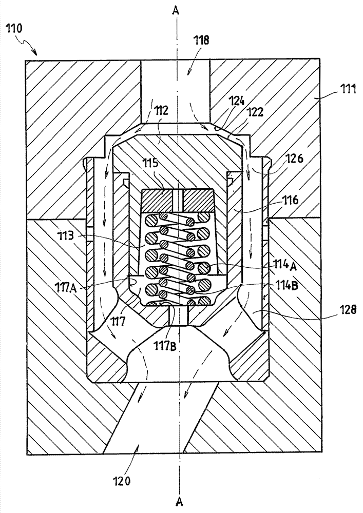
The invention relates to a differential pressure valve with parallel biasing springs and a method for reducing spring surge. The differential pressure valve is disclosed, comprising: a valve body (111), said valve body having at least one flow inlet (118) and one flow outlet (120); at least one shutter (112), said shutter being movable between an open position and a closed position under a differential pressure across the valve; a flow passage (126) from the flow inlet (118) to the flow outlet (120); at least one biasing member (114) configured to bias the shutter (112) towards a closed position so as to block the flow passage through the flow inlet (118). The biasing member (114) comprises at least two springs (114A, 114B) arranged in parallel, one of said springs having at least one resonance frequency different from at least one resonance frequency of the other of said two springs.

Description

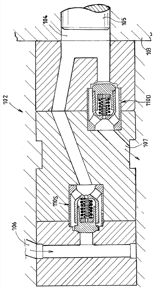
technical field [0001] The disclosed embodiments generally relate to differential pressure valves, ie, to valves that are automatically actuated by a pressure differential across the valve. Some exemplary embodiments relate in particular to reciprocating compressor valves, such as poppet valves of high pressure compressors in particular. Background technique [0002] Those high pressure compressors capable of producing gas pressure levels up to or exceeding 3000 bar are widely used in industrial applications including, but not limited to, the production of low density polyethylene or LDPE. The efficiency performance of these compressors is controlled at least in part by suction and discharge automatic poppet valves. FIG. 1 shows a section of a part of a conventional high-pressure compressor 2 comprising two poppet valves 10 . FIG. 2 shows an enlarged cross-section of a conventional poppet valve of the compressor shown in FIG. 1 in an open position. A poppet guide accordin...

Claims


Application Information

Patent Timeline
Patent Type & Authority Applications(China)
IPC IPC(8): F04B39/10F04B39/00
CPCF04B39/1013F16K17/044F04B39/10F16K15/12F16K15/026F16F1/047F04B39/1053G05D16/106G05D16/028Y10T137/0379Y10T137/7832F16K17/0433
Inventor R.巴加利C.马吉A.巴比尼L.托纳雷利
Owner NUOVO PIGNONE TECH SRL
Why Eureka
Try Eureka