
Hydrodynamically guided circular saw blade

A technology of circular saw blade and support body, which is applied to metal sawing equipment, attachments of sawing machines, tools of sawing machines, etc., can solve problems such as damage to the quality of the sawing process, and achieve the effect of reducing vibration and improving quality

Active Publication Date: 2013-01-09
ARNO FRIEDRICHS HARTMETALL GMBH & CO KG
View PDF7 Cites 3 Cited by
  • Summary
  • Abstract
  • Description
  • Claims
  • Application Information

AI Technical Summary

Problems solved by technology

[0003] A disadvantage of the known circular saw blades is that vibrations of the circular saw blade occur during the sawing process, which impair the quality of the sawing process

Method used


Image

  • Hydrodynamically guided circular saw blade
  • Hydrodynamically guided circular saw blade

Examples


Embodiment Construction

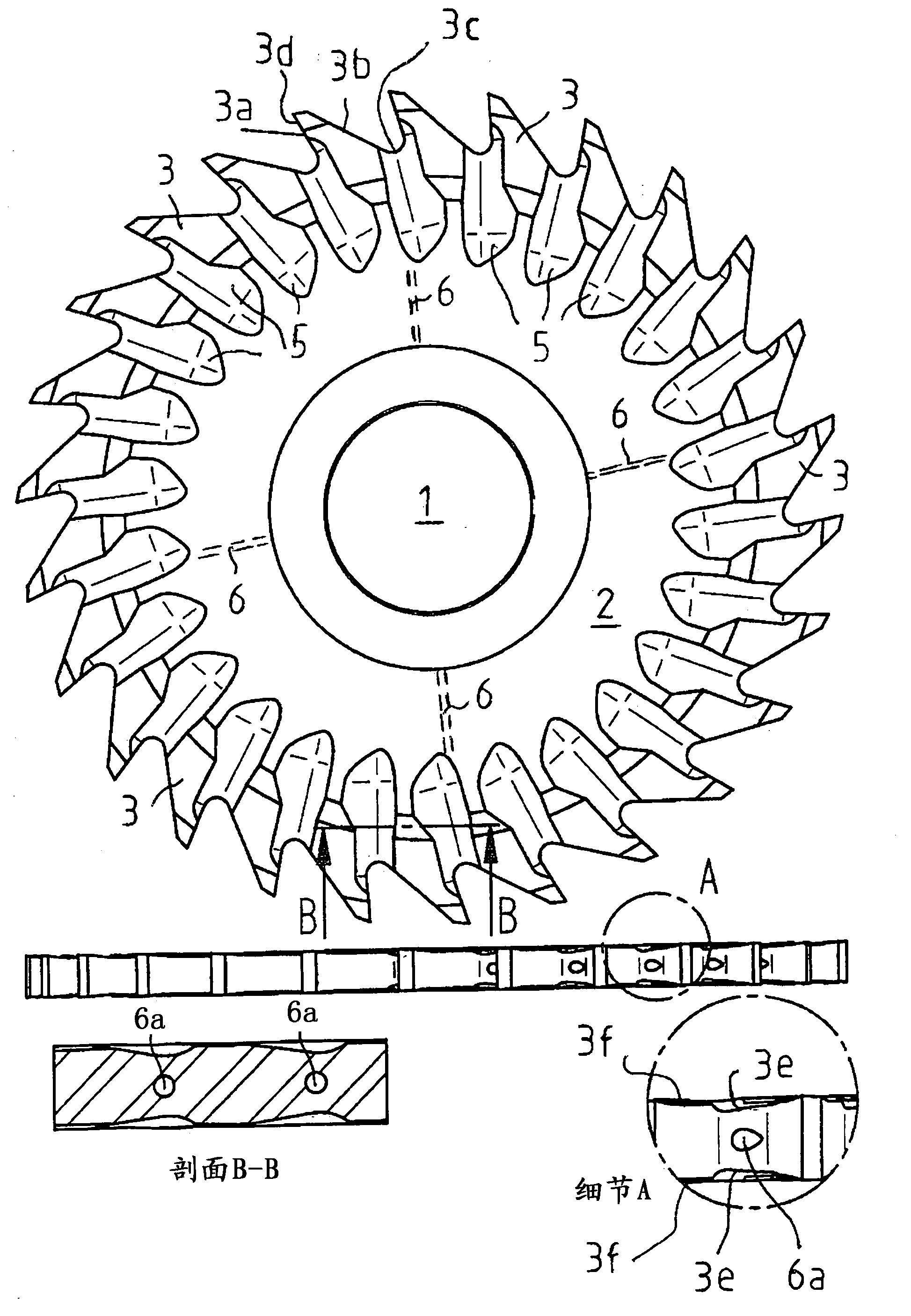
[0011] figure 1 A schematic view of a circular saw blade according to a first exemplary embodiment of the invention is shown. The circular saw blade has a central hole 1 in its central region, so that it can be fixed on a shaft of the circular saw. Furthermore, the circular saw blade includes a carrier body 2 made of cemented carbide, ceramic or steel. A plurality of cooling channels 6 distributed in the radial direction are arranged in the inner region of the carrier body 2, wherein, in figure 1 Only four of these cooling channels are marked with dashed lines in .

[0012] In the area of ​​the outer circumference of the carrier body 2 are provided a plurality of teeth 3 which each have a front flank 3a, a rear flank 3b, a dedendum 3c, a cutting edge 3d, a narrowing region 3e and a Again widened area 3f.

[0013] During saw operation, cooling fluid is conducted via the cooling channel 6 into the working region of the circular saw blade and is discharged there from the circ...


PUM


Abstract

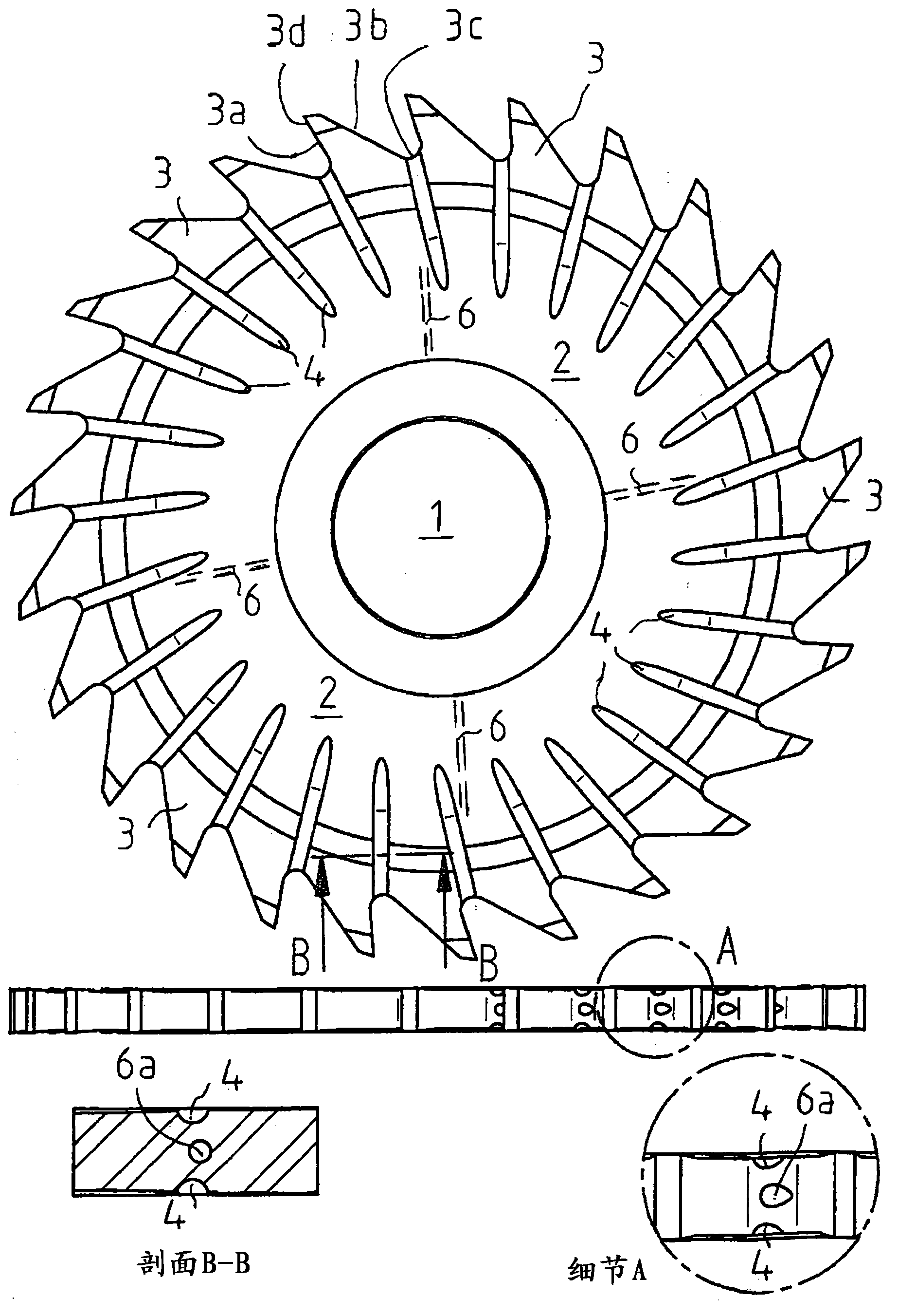
The invention relates to a circular saw blade, which comprises a supporting body (2), cooling channels (5) provided in the inner region of the supporting body (2) and running in the radial direction, and teeth (3) provided in the region of the outer periphery of the supporting body. The cooling channels (5) emerge from the circular saw blade in the region of the tooth bases (3c) or in the region of the flanks (3b) of the teeth (3). Furthermore, the circular saw blade has pockets (4) which, starting from a tooth base (3c) or a flank (3b) of a tooth (3), extend inwardly into the region of the supporting body (2).

Description

technical field [0001] The invention relates to a circular saw blade having cooling channels through which a coolant can be conveyed into the working area of ​​the circular saw blade during operation of the saw and at the root or teeth of the teeth of the circular saw blade discharge from the circular saw blade in the area of ​​the face to cool the working area. Background technique [0002] A circular saw blade with cooling channels extending in the radial direction is already known from DE 10 2007 022 310 A1, which circular saw blade is one-part and is made of hard metal, steel or ceramic. On the outer circumference of the circular saw blade, the teeth are inserted into the circular saw blade in such a way that the outlet openings of the cooling channels are located in the region of the tooth root or the middle of the tooth flank of the circular saw blade. [0003] A disadvantage of the known circular saw blades is that vibrations of the circular saw blade occur during th...

Claims


Application Information

Patent Timeline
Patent Type & Authority Applications(China)
IPC IPC(8): B23D59/02B23D61/02
CPCB23D59/02B23D61/021B23D61/025B23D61/02B23D61/04Y10T83/263
Inventor 阿尔诺·弗里德里希斯
Owner ARNO FRIEDRICHS HARTMETALL GMBH & CO KG
Learn More