White OLED luminophor
An illuminant, white technology, applied in the manufacture of electric solid devices, semiconductor devices, semiconductor/solid state devices, etc., can solve the problems of difficult process, difficult to manufacture white OLED light emitting devices, poor white spectral stability of OLED light emitting devices, etc. Ensure spectral stability, improve mass production yield, and ensure the effect of color stability
- Summary
- Abstract
- Description
- Claims
- Application Information
AI Technical Summary
Problems solved by technology
Method used
Image

Examples
Embodiment 1
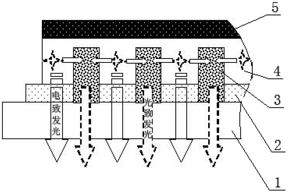
[0107] figure 1 Shown is the first structure of the white OLED luminous body of the present invention, which includes an OLED light-emitting device and a transparent substrate 1, and the OLED light-emitting device includes a transparent conductive electrode layer 2, an organic light-emitting functional material film layer combination 4 and a reflective electrode Layer 5, the OLED light-emitting device can generate electroluminescence when it is powered on, and the electroluminescent light-emitting spectrum at least includes blue light-emitting components with a CIE color coordinate Y value of less than 0.55; the transparent OLED light-emitting device The conductive electrode layer 2 is arranged on the transparent substrate 1, the color changing material 3 is arranged between the reflective electrode layer 5 of the OLED light-emitting device and the transparent substrate 1, and the color changing material 3 directly covers the surface of the transparent plate 1 and the reflecti...
Embodiment 2
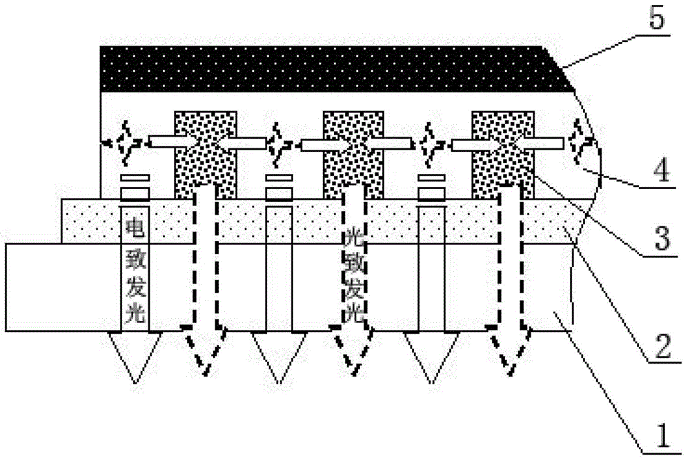
[0164] figure 2 Shown is the second structure of the white OLED luminous body of the present invention, which is the same as figure 1 The structural form shown is different in that the color changing material 3 of the white OLED luminous body is arranged between the transparent conductive film layer and the reflective electrode layer 5, and the color changing material 3 does not contact the glass substrate. The color-changing material 3 in this structural form can also strongly absorb the electroluminescence that is bound in the OLED light-emitting device and propagates laterally in the form of guided waves and cannot be effectively extracted, and converts it into low-energy photoluminescence. The photoluminescence is reflected by the reflective electrode layer 5 and then directed toward the transparent substrate 1, and the photoluminescence emitted from the transparent substrate 1 is mixed with the electroluminescence emitted from the transparent substrate 1 to form the whit...
manufacture Embodiment 1
[0166] Manufacturing steps process:
[0167] (1) In the form of entrusted processing, the etched ITO transparent substrate 1 (film impedance is 9 ohm / □) was obtained from Chunghwa Picture Tubes Co., Ltd. (headquartered in Taiwan), and the ITO on the ITO transparent substrate 1 was divided into widths It is a 1.5 cm strip grid line, and the spacing between each grid line is 1 mm.
[0168] (2) Set the color changing material 3 on the above-mentioned ITO transparent substrate 1: In this manufacturing example, the color changing material 3 is processed by a wet process method, the color changing material 3 is a green color changing material, and the green color The change material is arranged on the ITO transparent substrate 1 in the form of photoresist, specifically, the green color change material 3 is dispersed into the transparent photoresist and processed by traditional photolithography process. The photoresist material used in this manufacturing example is a transparent p...
PUM
| Property | Measurement | Unit |
|---|---|---|
| Width | aaaaa | aaaaa |
| Thickness | aaaaa | aaaaa |
| Thickness | aaaaa | aaaaa |
Abstract
Description
Claims
Application Information
 - R&D
- Intellectual Property
- Life Sciences
- Materials
- Tech Scout
- Unparalleled Data Quality
- Higher Quality Content
- 60% Fewer Hallucinations
Browse by: Latest US Patents, China's latest patents, Technical Efficacy Thesaurus, Application Domain, Technology Topic, Popular Technical Reports.
© 2025 PatSnap. All rights reserved.Legal|Privacy policy|Modern Slavery Act Transparency Statement|Sitemap|About US| Contact US: help@patsnap.com