
Satellite attitude determination method and attitude determination error analytical method based on two star sensors

A dual-star sensor, satellite attitude technology, applied in astronomical navigation, navigation calculation tools and other directions, can solve problems such as large measurement error and no attitude error

Active Publication Date: 2013-01-09
哈尔滨工大卫星技术有限公司
View PDF3 Cites 24 Cited by
  • Summary
  • Abstract
  • Description
  • Claims
  • Application Information

AI Technical Summary

Problems solved by technology

[0004] The present invention solves the problem that the existing measuring error around the optical axis of the star sensor is large and there is no analysis method for the attitude determination error, and further provides a satellite attitude determination method and an attitude determination error analysis method based on a double-star sensor

Method used


Image

  • Satellite attitude determination method and attitude determination error analytical method based on two star sensors
  • Satellite attitude determination method and attitude determination error analytical method based on two star sensors
  • Satellite attitude determination method and attitude determination error analytical method based on two star sensors

Examples


specific Embodiment approach 1

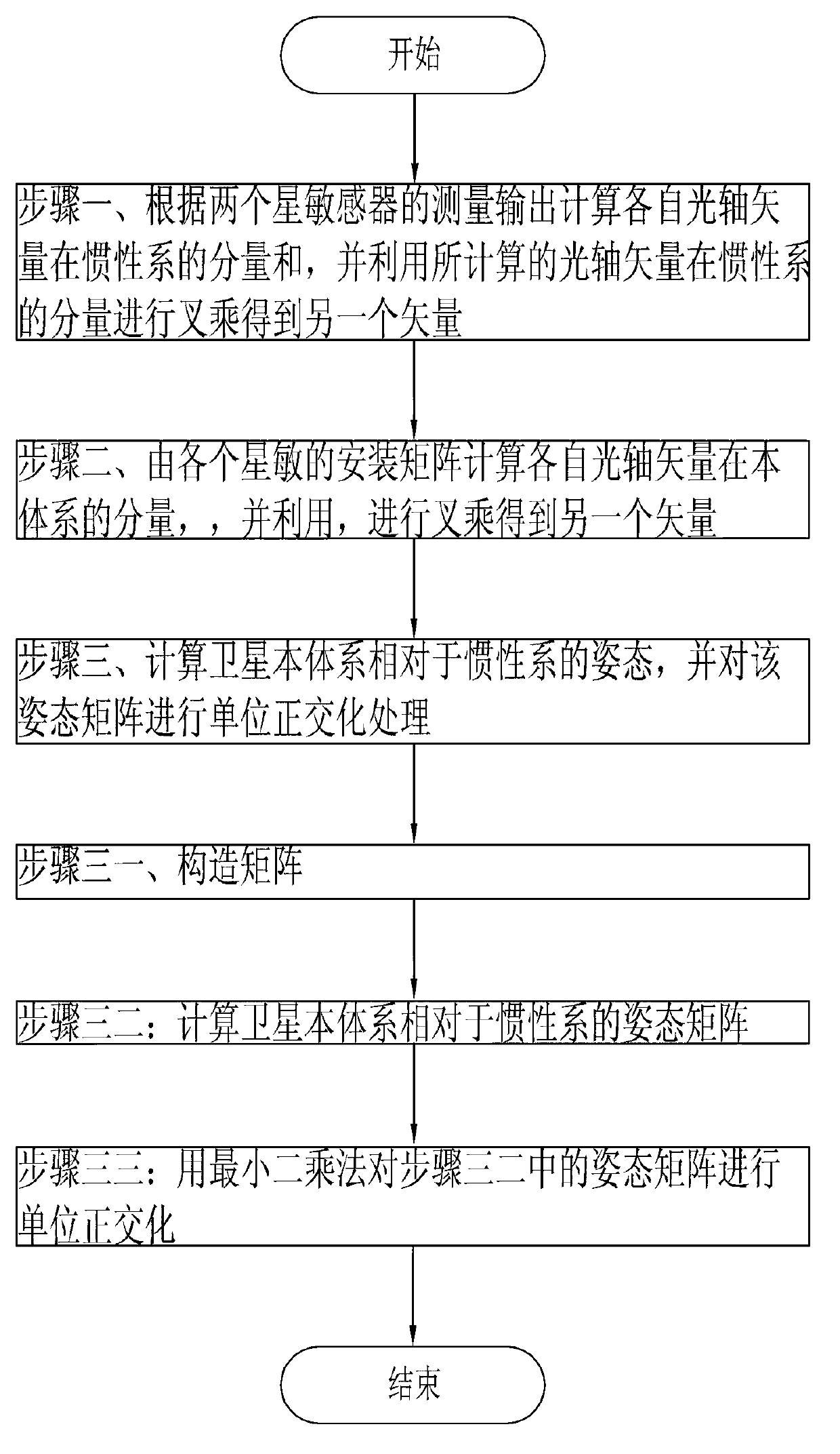
[0075] Specific implementation mode one: as figure 1 , image 3 and Figure 4 As shown, the satellite attitude determination method based on the double star sensor of the present embodiment is realized by the following steps:

[0076] Step 1. Calculate the components of the respective optical axis vectors in the inertial system according to the measurement outputs of the two star sensors and And use the calculated optical axis vector in the inertial system to perform cross product to get another vector The specific process is as follows:

[0077] The product of the component of the optical axis vector in the inertial system and the component of the optical axis vector in the inertial system is as follows:

[0078] L A i * = C iA * L A A , L ...

specific Embodiment approach 2

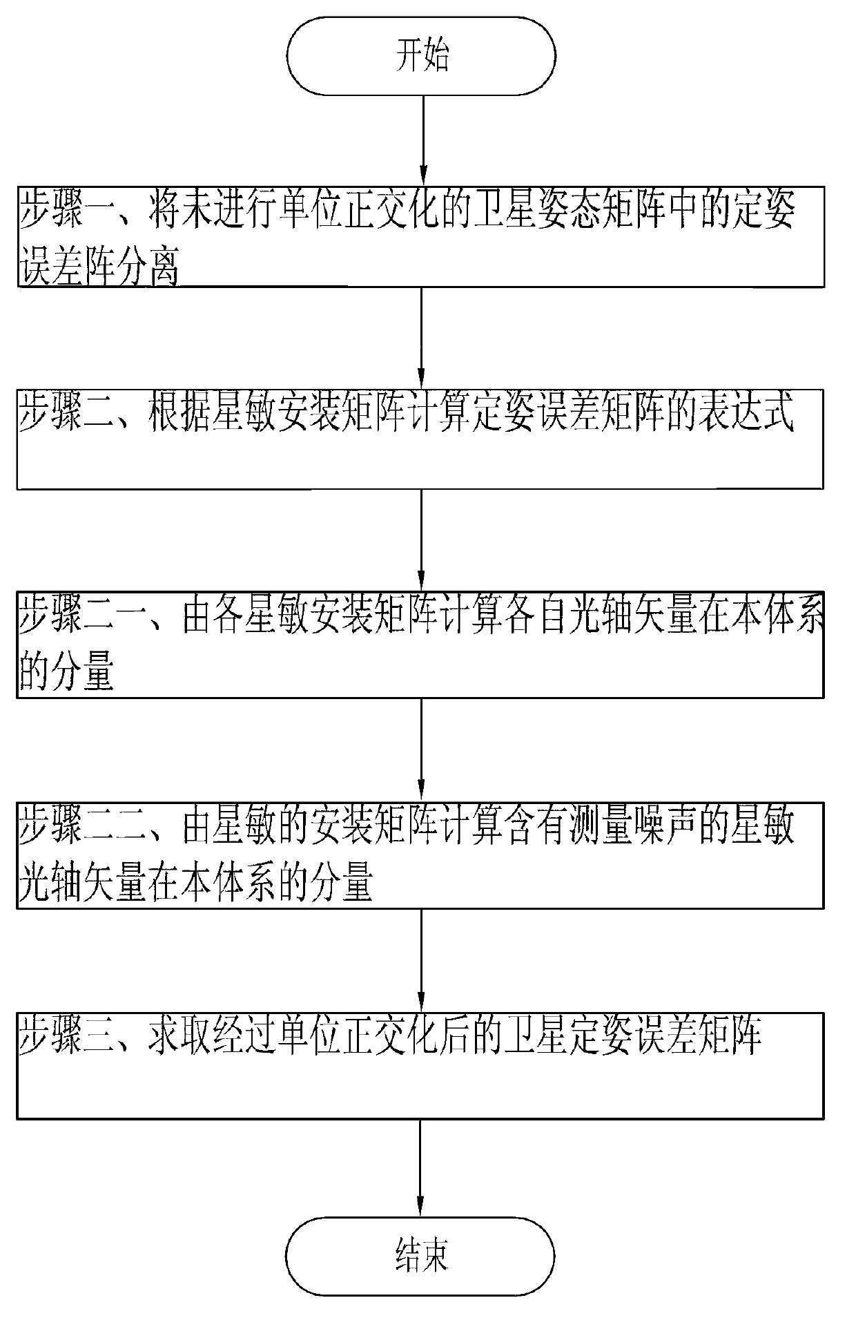
[0098] Specific implementation mode two: as Figure 2-4 As shown, the satellite attitude error analysis method based on the double star sensor of the present embodiment is realized by the following steps:

[0099] Step 1. Orthogonalize the satellite attitude matrix without unit The attitude error matrix C in * Separation:

[0100] According to the relationship of each attitude matrix:

[0101] L 3 × 3 i * = L A i * L B i * L C i ...

specific Embodiment

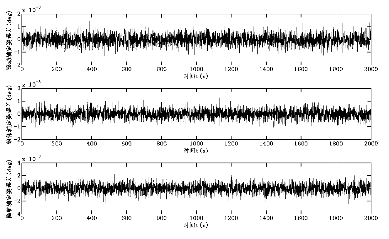
[0143] Adopt concrete parameter, implement the parameter design process of variable structure control algorithm of the present invention, and control result:

[0144] This example provides the installation matrix of the double star sensor as follows:

[0145] C bA = 0.2435 - 0.9427 0.2281 - 0.8238 - 0.3251 - 0.4643 0.5119 - 0.0749 - 0.8558 , C bB = ...


PUM


Abstract

The invention relates to a satellite attitude determination method and an attitude determination error analytical method, in particular to a satellite attitude determination method and an attitude determination error analytical method based on two star sensors, and aims at solving the problems that the existing measuring error in the star sensor optical axis direction is large and presently no attitude determination error analytical method exists. The first scheme is that the component of the optical axis vector of each star sensor in an inertial system is calculated according to measuring output of the two star sensors, the component of the optical axis vector of each star sensor in a satellite body system is calculated according to an installation matrix of each star sensor, the gesture of the satellite body system relative to the inertial system is calculated, and a gesture matrix is subjected to unit orthogonalization processing. The second scheme is that an attitude determination error matrix C* in the satellite gesture matrix and not subjected to unit orthogonalization is separated; the expression of the attitude determination error matrix C* is evaluated according to the star sensor installation matrixes; and a satellite attitude determination error matrix delta C subjected to unit orthogonalization is gained. The satellite attitude determination method and the attitude determination error analytical method are used for satellite attitude determination and attitude determination error analyzing.

Description

technical field [0001] The invention relates to a satellite attitude determination method and an error analysis method for the attitude determination. Background technique [0002] Among all kinds of satellite attitude sensors, the measurement information of star sensors is the most accurate. With the further exploration of space, higher requirements are placed on the accuracy of satellite attitude determination and control. Therefore, star sensors are used in satellite attitude Make sure the system is getting more and more used. The star sensor can provide the three-axis attitude of the star-sensitive measurement coordinate system relative to the inertial system. However, in the three-axis measurement information provided by the star sensor, the measurement error in the direction around the star-sensitive optical axis is often large, and the direction around the star-sensitive optical axis The measurement error is several times that of other directions, so how to improve t...

Claims


Application Information

Patent Timeline
IPC IPC(8): G01C21/02G01C21/20
Inventor 耿云海侯志立张春阳李诚良
Owner 哈尔滨工大卫星技术有限公司
Learn More