Backlight module

A technology for a backlight module and a back frame, applied in the field of backlight modules, can solve the problems of troublesome light blocking unit 900, display problems of display devices, unfavorable cost control, etc., and achieve the effects of simple structure, cost control, and saving a lot of time

Inactive Publication Date: 2013-01-09
TCL CHINA STAR OPTOELECTRONICS TECH CO LTD
View PDF5 Cites 9 Cited by
  • Summary
  • Abstract
  • Description
  • Claims
  • Application Information

AI Technical Summary

Problems solved by technology

[0003] like figure 1 As shown, it is a structural schematic diagram of an existing liquid crystal display device, which includes a front frame 100, a rear frame 300 cooperating with the front frame 100, and a liquid crystal display device arranged between the front frame 100 and the rear frame 300. The panel 500 and the backlight module 700 located between the front frame 100 and the rear frame 300 and below the liquid crystal display panel 500, there is also a black adhesive material between the liquid crystal display panel 500 and the backlight module 700 The formed light sealing unit 900 is fixed on the diffuser plate 702 of the backlight module 700 adjacent to the non-display area 502 of the liquid crystal display panel 500 to prevent light leakage, but the light sealing unit 900 is pasted on The process on the diffuser plate 502 is cumbersome, and it is easy to cause the light sealing unit 900 to stick to the deviation, so that part of the light sealing unit 900 blocks the display area 504 of the liquid crystal display panel 500, resulting in display problems of the liquid crystal display device.
[0004] like figure 2 As shown, it is a structural schematic diagram of an existing backlight module 500', the backlight module 500' includes: a back frame 520', a light source 540' set in the back frame 520', a light source set in the back frame 520' The reflective sheet 560', the light guide plate 580' provided on the reflective sheet 560', the optical film group 590' provided on the light guide plate 580', and the plastic frame 530' provided on the back frame 520', the plastic frame 530' is made of highly reflective polycarbonate mixed with 10% titanium oxide. The back frame 520' is made of polycarbonate. The plastic frame 530' has both reflective and light-blocking properties. The back frame 520' With good reflectivity, it solves the figure 1 The problem of backlight light leakage ensures that the backlight has a high light utilization rate, but the cost of mixing 10% titanium oxide with polycarbonate, a highly reflective material, is high, which is not conducive to cost control

Method used


Image

  • Backlight module
  • Backlight module
  • Backlight module

Examples


Embodiment Construction

[0023] In order to further illustrate the technical means adopted by the present invention and its effects, the following describes in detail in conjunction with preferred embodiments of the present invention and accompanying drawings.

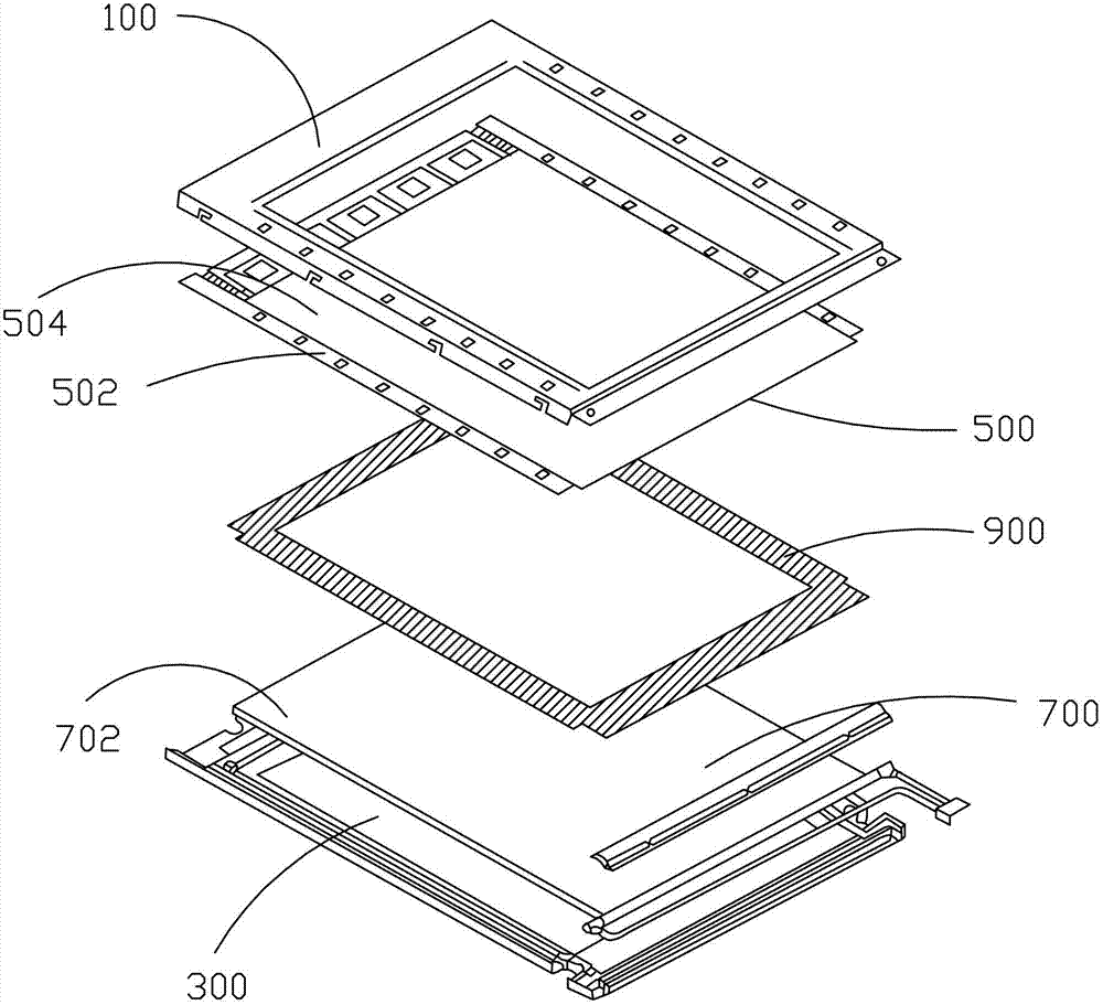
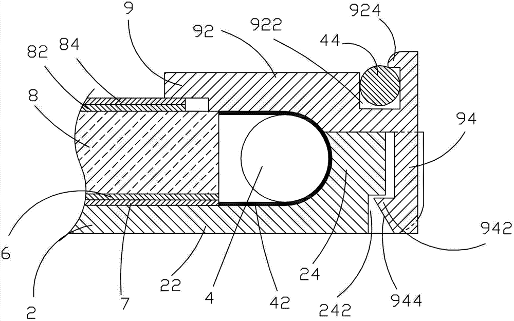
[0024] see image 3 , the present invention provides a backlight module, comprising: a back frame 2, a light source 4 arranged in the back frame 2, a reflective sheet 6 arranged in the back frame 2, a light guide plate 8 arranged on the reflective sheet 6, and a device The plastic frame 9 on the back frame 2, the position corresponding to the light source 4 on the back frame 2 and the plastic frame 9 is coated with a high reflective material layer 42, and the high reflective material layer 42 reflects the light emitted by the light source 4 to make it more transparent. More light enters the light guide plate 8 to effectively improve light utilization efficiency. In this embodiment, the high reflection material used is aluminum powder, and the ...


PUM


Abstract

The invention provides a backlight module which comprises a back frame, a light source arranged in the back frame, a reflection piece arranged in the back frame, a light guide plate arranged on the reflection piece and a rubber frame arranged on the back frame. A high-reflection material layer is respectively coated on the back frame and the rubber frame at the positions corresponding to the light source, so that the backlight module improves light utilization rate, and is simple in structure, less in usage of the high-reflection materials and capable of effectively controlling cost. Further, the back frame and the rubber frame are connected in clamping mode, so that the backlight module is convenient to assemble and disassemble, saves a large amount of time, improves production efficiency and further reduces production cost.

Description

technical field [0001] The invention relates to the field of liquid crystal display, in particular to a backlight module. Background technique [0002] A liquid crystal display (LCD, Liquid Crystal Display) has many advantages such as a thin body, power saving, and no radiation, and has been widely used. Most of the liquid crystal display devices currently on the market are backlight liquid crystal display devices, which include a liquid crystal panel and a backlight module. The working principle of the liquid crystal panel is to place liquid crystal molecules between two parallel glass substrates. There are many vertical and horizontal small wires between the two glass substrates. The direction of the liquid crystal molecules is controlled by electrifying or not, and the light of the backlight module is refracted. Come out to generate the picture. Since the liquid crystal panel itself does not emit light, the light source provided by the backlight module is needed to disp...

Claims


Application Information

Patent Timeline
Patent Type & Authority Applications(China)
IPC IPC(8): F21S8/00F21V17/10F21V7/22G02F1/13357
CPCG02B6/0031G02B6/0055G02B6/009G02F1/133615G02F2201/34
Inventor 俞刚顾毓波杨流洋
Owner TCL CHINA STAR OPTOELECTRONICS TECH CO LTD
Why Eureka
Try Eureka