Ultrasonic fat-reducing device
An ultrasound, ultrasonic technology, applied in ultrasonic therapy, medical science, treatment and other directions, can solve problems such as injury and human tissue damage
- Summary
- Abstract
- Description
- Claims
- Application Information
AI Technical Summary
Problems solved by technology
Method used
Image
Examples
Embodiment 1
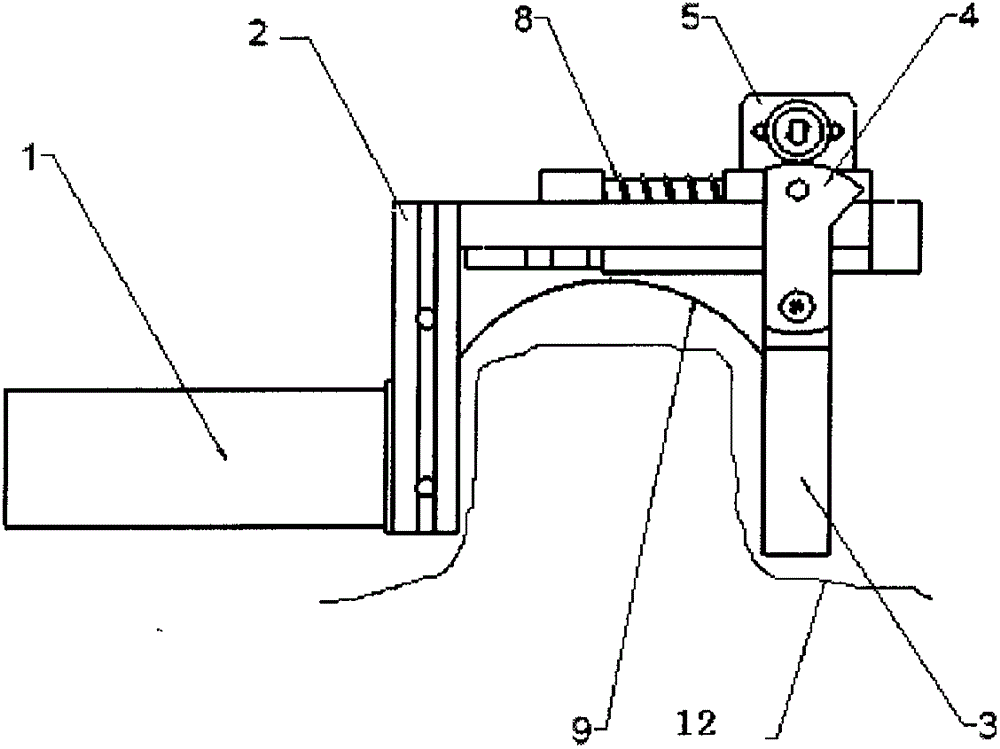
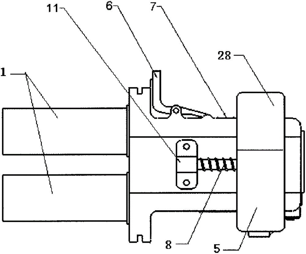
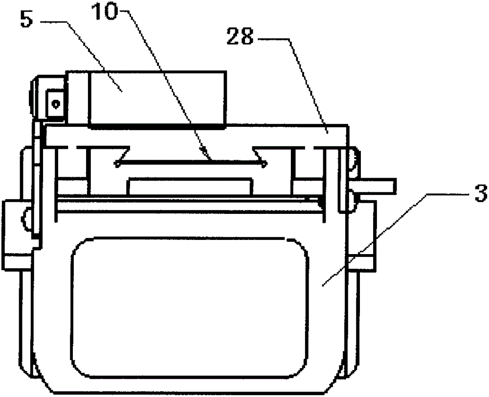
[0059] Such as Figure 1 to Figure 4 As shown, in this embodiment, the ultrasonic fat reduction device includes a host and a treatment mechanism connected to the host, and the treatment mechanism includes an ultrasonic transducer 1 and a clamping unit for clamping the skin, wherein the ultrasonic transducer 1 adopts a transmitter The planar ultrasonic transducer of the planar ultrasonic wave, that is, the ultrasonic wave emitted by the ultrasonic transducer 1 is a planar ultrasonic wave, and the position of the ultrasonic transducer in the treatment mechanism is set so that the planar ultrasonic wave emitted by it can just be clamped by the clamping unit. A standing ultrasonic wave is formed at the held skin location.
[0060] In the ultrasonic fat reducing device of this embodiment, by using two beams of the same frequency of ultrasonic waves to converge in a certain area, coherent ultrasonic waves (standing waves) are generated in the intersection area, so that the fat tissu...
Embodiment 2
[0081] The difference between this embodiment and Embodiment 1 lies in that the location of the auxiliary clamping drive unit is different, and other structures and usages in this embodiment are the same as those in Embodiment 1, and will not be repeated here.
[0082] In Embodiment 2, the auxiliary clamping drive unit includes a motor 5 , a gear pair 4 and a roller 13 to provide power. The gear pair 4 includes a driving wheel and a driven wheel meshing with the driving wheel. The gear pair 4 and the motor 5 are arranged outside the lower part of the second clamping plate 3 ; the rollers 13 are arranged at the lower end of the second clamping plate 3 . The driving wheel in the gear pair 4 is connected with the output shaft of the motor 5, and the driven wheel meshes with the roller 13. The motor 5 rotates to drive the driving wheel in the gear pair 4 to rotate, the driving wheel drives the driven wheel to rotate, and the driven wheel drives the roller 13 to rotate. When the s...
Embodiment 3
[0084] Such as Figure 8 , 9 As shown, in this embodiment, the clamping unit includes a handle 14, a fixed bracket, a pulling plate 18 capable of absorbing skin, two splints 17, and a movable bracket.
[0085] Described fixed bracket comprises connecting arm 29 and two fixed clamp arms 20, and the middle part of connecting arm 29 is fixedly connected with handle 14, and two fixed clamp arms 20 are symmetrically arranged at the two ends of connecting arm 29, and two fixed clamp arms 20 The upper ends of the upper ends are respectively fixedly connected with the two ends of the connecting arm 29. Described movable support comprises upper arm 19, the sleeve 15 that is fixedly arranged on upper arm 19 middle parts, and two movable pliers arms 16, and two movable pliers arms 16 are symmetrically arranged at the two ends of upper arm 19, and the two movable pliers arms 16 The upper end is respectively hinged with the two ends of the upper arm 19, so that the movable pliers arm 16 ...
PUM
 Abstract
Description
Claims
Application Information
 - R&D
- Intellectual Property
- Life Sciences
- Materials
- Tech Scout
- Unparalleled Data Quality
- Higher Quality Content
- 60% Fewer Hallucinations
Browse by: Latest US Patents, China's latest patents, Technical Efficacy Thesaurus, Application Domain, Technology Topic, Popular Technical Reports.
© 2025 PatSnap. All rights reserved.Legal|Privacy policy|Modern Slavery Act Transparency Statement|Sitemap|About US| Contact US: help@patsnap.com


