Inverter control device, electric compressor using inverter control device, and electric equipment
A control device and inverter technology, applied in control systems, electronic commutation motor control, single motor speed/torque control, etc. Brush DC motor operation control and other issues to achieve high operation control, suppression of misalignment stop, stable and reliable effects
- Summary
- Abstract
- Description
- Claims
- Application Information
AI Technical Summary
Problems solved by technology
Method used
Image
Examples
Embodiment approach 1
[0032] [Basic structure of inverter control unit]
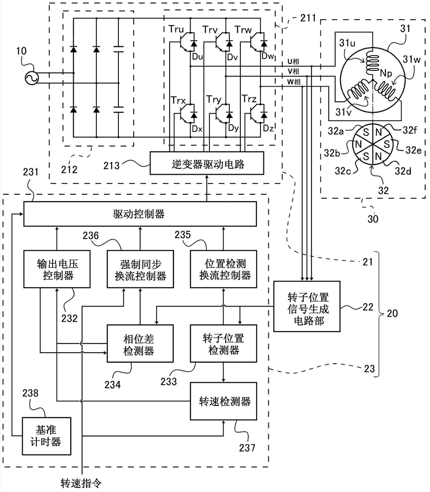
[0033] First, refer to figure 1 An example of the configuration of the inverter control device according to Embodiment 1 of the present invention will be specifically described.
[0034] like figure 1 As shown, the inverter control device 20 of this embodiment is a device that controls the operation of the brushless DC motor 30 and includes an inverter circuit unit 21 , a rotor position signal generation circuit unit 22 , and an inverter control unit 23 .
[0035] The brushless DC motor 30 set as the control object by the inverter control device 20 is a three-phase permanent magnet synchronous motor, such as figure 1 As shown, a stator 31 composed of three-phase windings and a rotor 32 including permanent magnets 32a to 32f are included.
[0036] The stator 31 includes a stator winding 31u corresponding to the U phase, a stator winding 31v corresponding to the V phase, and a stator winding 31w corresponding to the W phase. ...
Embodiment approach 2
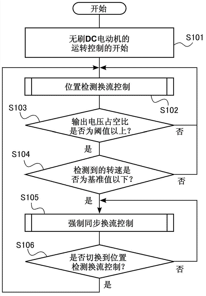
[0119] In Embodiment 1 described above, the drive controller 231 can switch control under any conditions when returning from forced synchronous commutation control to position detection commutation control (see image 3 step S106). On the other hand, in Embodiment 2, the drive controller 231 may be configured such that the forced synchronous commutation control returns to the position detection commutation control based on the rotational speed command, for example. Next, this structure will be specifically described.
[0120] like figure 1 As shown, the inverter control device 20 according to the second embodiment has the same configuration as that described in the above-mentioned first embodiment, and therefore a specific description thereof will be omitted. Here, in the inverter control device 20 of the present embodiment, when the drive controller 231 controls the commutation of the PWM inverter 211 based on the forced synchronous commutation signal (that is, the forced s...
Embodiment approach 3
[0130] In Embodiment 1 or 2 above, an example in which the inverter control device 20 is used to control the sensorless operation of the brushless DC motor 30 has been described. The inverter control device 20 of or 2, the electric compressor of the brushless DC motor 30 whose operation is controlled by the inverter control device 20, and the refrigerator including the electric compressor will be specifically described.
[0131] [Structure Example of Electric Compressor]
[0132] The inverter control device 20 of Embodiment 1 or 2 described above can be preferably used for an electric compressor included in a refrigerator. refer to Figure 8A The electric compressor will be specifically described.
[0133] like Figure 8A As shown, the electric compressor 40 is equipped with the inverter circuit part 21 of Embodiment 1 or 2, the inverter control part 23, the brushless DC motor 30, and the compression mechanism 41. The inverter control device 20 is constituted by an inverte...
PUM
 Abstract
Description
Claims
Application Information
 - R&D Engineer
- R&D Manager
- IP Professional
- Industry Leading Data Capabilities
- Powerful AI technology
- Patent DNA Extraction
Browse by: Latest US Patents, China's latest patents, Technical Efficacy Thesaurus, Application Domain, Technology Topic, Popular Technical Reports.
© 2024 PatSnap. All rights reserved.Legal|Privacy policy|Modern Slavery Act Transparency Statement|Sitemap|About US| Contact US: help@patsnap.com


