
Measuring device of high-temperature superconductive suspension tiny force

A measuring device, high-temperature superconducting technology, applied in measuring devices, force/torque/work measuring instruments, instruments, etc., can solve thruster tests that are not suitable for large masses, performance limitations of optical fiber tensile strength, and increased friction And other issues

Inactive Publication Date: 2013-01-02
BEIHANG UNIV
View PDF4 Cites 33 Cited by
  • Summary
  • Abstract
  • Description
  • Claims
  • Application Information

AI Technical Summary

Problems solved by technology

However, due to the limitation of the tensile strength performance of the optical fiber, the system is not suitable for the thruster test with a large mass
In addition, foreign countries have also developed double-pendulum and multi-pendulum thrust measurement systems, which can measure the micro-thrust of heavier thrusters, but the disadvantage is that multiple movable joints (Pivots) are used, so the friction increases. When testing a single pulse, Displacement vibration signal attenuates quickly
After years of development, the latter technology is relatively mature and has been applied to multiple sets of micro-thrust measurement devices. However, its significant defect is that its bearing capacity is limited

Method used


Image

  • Measuring device of high-temperature superconductive suspension tiny force
  • Measuring device of high-temperature superconductive suspension tiny force
  • Measuring device of high-temperature superconductive suspension tiny force

Examples


Embodiment Construction

[0040] The present invention will be further described in detail with reference to the accompanying drawings and embodiments.

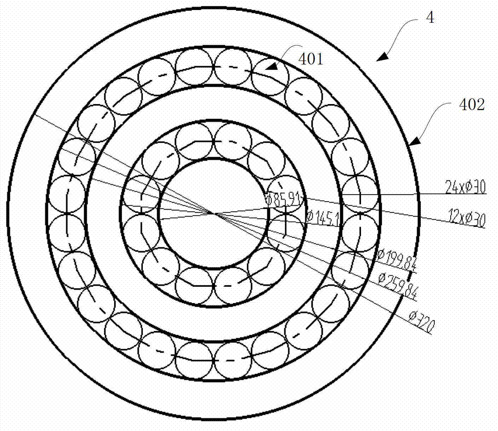
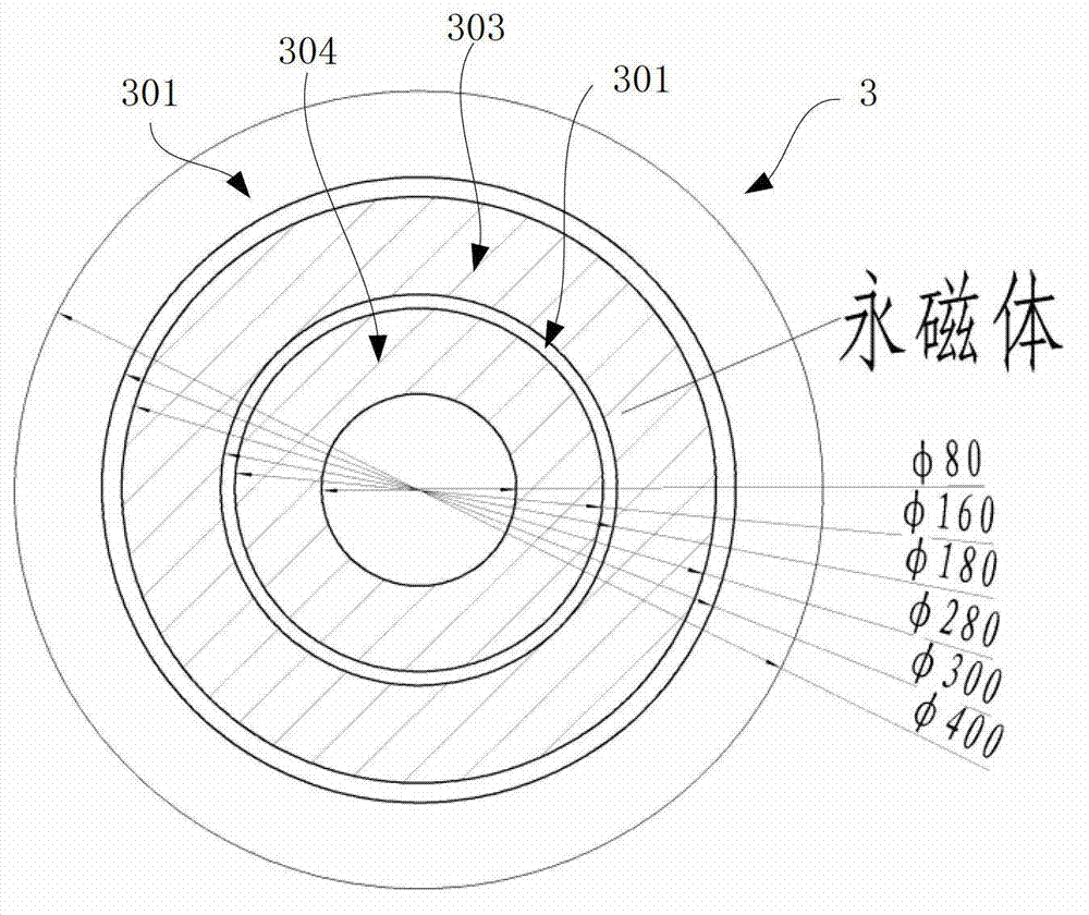
[0041] The invention is a high-temperature superconducting suspension micro-force measuring device, such as figure 1 As shown, it includes a vacuum chamber 1, a high-speed camera 2, a permanent magnet platform 3, a superconductor platform 4, a cryogenic system 5, a calibration striker structure 6, a CCD laser speedometer 7 and a floating mechanism 8.

[0042]The cryogenic system 5 is fixed at the bottom of the vacuum chamber 1 , the superconductor platform 4 is located at the upper end of the cryogenic system 5 , and the cryogenic system 5 implements cryogenic cooling of the superconductor platform 4 . An epoxy resin cover with a thickness of 3 mm is also arranged above the superconductor platform 4 to produce a pressing effect on the upper surface of the superconductor.

[0043] The superconductor platform 4 includes a superconductor 401 and a struc...


PUM


Abstract

The invention discloses a measuring device of a high-temperature superconductive suspension tiny force. The measuring device comprises a vacuum cabin, a high-speed camera, a permanent magnet platform, a superconductor platform, a low temperature system, a calibration firing pin, a charge coupled device (CCD) laser speed detector and a floating mechanism; different firing calibration forces are provided through a calibration firing pin structure; then four configured CCD laser displacement sensors respectively obtain the vibration data along the vertical direction and the horizontal direction of a permanent magnet platform corresponding to different calibration forces, thereby forming an one-to-one corresponding relationship of the calibration force and the permanent magnet platform movement. When the tiny thrust of an electric thruster is acted on the permanent magnet platform, the CCD laser displacement sensor can obtain the vibration properties on the vertical and horizontal directions of the permanent magnet platform; then the tiny thrust of the electric thruster can be calculated according to the obtained one-to-one corresponding relationship of the calibration force and the permanent magnet platform movement.

Description

technical field [0001] The patent of the present invention relates to a thrust measuring device, especially a high-temperature superconducting suspension micro-force measuring device capable of identifying small thrust and tiny impulse. Background technique [0002] With regard to micro-thrust measurement, various current methods mostly use the scheme of torsion element support, vertical soft connection and measurement of dynamic response. The small thrust of the electric thruster is a very unstable small force value, and the introduction of the circuit and gas path when the thruster is working will cause additional errors, and the measurement interference caused by the heating of the thruster itself is also difficult to solve. Therefore, it is currently agreed that conventional force measurement methods using strain gauges or semiconductor force sensors to directly measure thrust are basically unfeasible. The reason is that such small-scale force sensors are very sensitive ...

Claims


Application Information

Patent Timeline
IPC IPC(8): G01L5/00
Inventor 玉龙杨文将刘宇
Owner BEIHANG UNIV
Learn More