
Hanging cable guiding device and method

A technology of guiding device and steel strand, applied in the erection/assembly of bridges, buildings, bridge construction, etc., can solve the problems of large construction quantity, manual switching, labor cost, etc., and achieve the effect of fast construction speed and high turnover times.

Active Publication Date: 2013-01-02
CHINA RAILWAY SHANGHAI ENGINEERING BUREAU GROUP CO LTD +1
View PDF8 Cites 4 Cited by
  • Summary
  • Abstract
  • Description
  • Claims
  • Application Information

AI Technical Summary

Problems solved by technology

In the Huangshan Huashan Bridge project constructed by our company, the cable-stayed cables of the cable-stayed bridge are arranged in a single tower and double-cable plane fan shape. There are 19 pairs on both sides of the north and south banks. There are 76 cables in the whole bridge. The types of cables are divided into 37, 43, 55 types, the total number of single hanging cables in the whole bridge is 3748, and the stay cables are constructed using a single, symmetrical hanging cable method, and single-ended tension is carried out at the tower end. From the above data, it can be seen that the construction quantity of this project is Large, if the traditional hanging cable guide device is used, the device cannot directly extend into the anchor head at the tower end, and it needs to be manually switched outside the tower, which will affect the hanging cable speed and consume redundant labor. During the operation, the construction requirements can be barely met when the short cables are hung in the early stage, but it still consumes excess labor and cannot meet the construction requirements in the later stage

Method used


Image

  • Hanging cable guiding device and method
  • Hanging cable guiding device and method
  • Hanging cable guiding device and method

Examples


Embodiment Construction

[0028] In order to make the technical content of the present invention clearer, it will be further elaborated in conjunction with the drawings and embodiments, and the structure of the related devices can be realized by those skilled in the art.

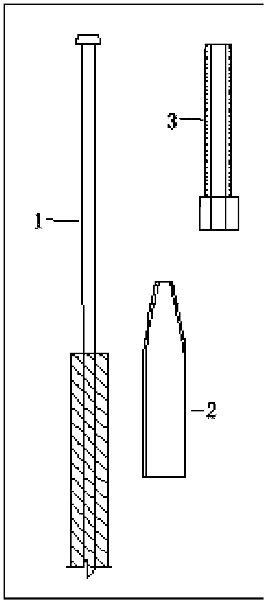
[0029] The present invention makes a structural improvement on the basis of the existing cable guide device, and the structure of the guide device obtained is as follows: figure 1 As shown, it includes threaded sleeves, steel ropes, high-strength bolts, steel wire ropes and high-strength screws. The steel ropes are 7-wire steel strands, which are characterized in that 1 wire Stranded wire, 1 steel strand at the left end is inserted into the first threaded sleeve 4, the end of the 1 steel strand at the left end is provided with a first pier head 5, the 1 steel strand at the right end passes through the second high-strength bolt 6, and the 1 steel strand at the right end passes through the second high-strength bolt 6. The end of the wi...


PUM


Abstract

The invention relates to the technical field of bridge construction and in particular relates to a hanging cable guiding device and method. The device comprises threaded sleeves, a strand rope, high-strength bolts, a steel wire rope and high-strength screws, wherein the strand rope comprises seven steel strands. The device is characterized in that one steel strand is respectively arranged at each of two ends of the strand rope: the steel strand at the left end is sleeved into the first threaded sleeve; the end of the steel strand at the left end is provided with a first pier head; the steel strand at the right end penetrates through the second high-strength bolt; the end of the steel strand at the right end is provided with a second pier head; the second high-strength bolt is screwed in the second threaded sleeve; the steel wire rope of a winch penetrates in the second threaded sleeve; and the second threaded sleeve and the steel wire rope are fixed by adopting the high-strength screws. The device disclosed by the invention combines the advantages of various traditional hanging cable guiding devices, has the characteristics of rapid construction speed, high turnover number, safety and reliability and has certain development and application value.

Description

[technical field] [0001] The invention relates to the technical field of bridge construction, in particular to a novel hanging cable guiding device and method suitable for cable-stayed bridges. [Background technique] [0002] Cable-stayed bridge, also known as cable-stayed bridge, is a bridge in which the main girder is directly pulled on the bridge tower by many cables. The structural system can be regarded as a multi-span elastically supported continuous beam with cables instead of buttresses. Generally, a cable-stayed bridge with a span of 300-1000m is suitable. In this span range, compared with a suspension bridge, a cable-stayed bridge has obvious advantages. Specifically, it can reduce the bending moment in the beam body and reduce the construction Height, reduce the weight of the overall structure, and save materials. F.leonhardt, a famous German bridge expert, believes that even a cable-stayed bridge with a span of 1400m can save half of the high-strength steel wire...

Claims


Application Information

Patent Timeline
IPC IPC(8): E01D19/16E01D21/00
Inventor 万志勇李明华孙东晓王靖陈恩东
Owner CHINA RAILWAY SHANGHAI ENGINEERING BUREAU GROUP CO LTD
Learn More