
Desalination method and device in petroleum sulfonate production

A petroleum sulfonate and desalination technology, applied in chemical instruments and methods, water/sewage multi-stage treatment, chilled water/sewage treatment, etc., can solve the problems of low processing capacity, resource waste environment, and long time consumption, and achieve automation High degree, saving production cost, avoiding the effect that cannot be deposited

Active Publication Date: 2013-01-02
SHANDONG DAMING FINE CHEM CO LTD
View PDF4 Cites 1 Cited by
  • Summary
  • Abstract
  • Description
  • Claims
  • Application Information

AI Technical Summary

Problems solved by technology

Due to the existence of a large amount of inorganic salts, the wastewater cannot be recycled, and direct discharge will not only cause waste of resources but also cause serious environmental pollution problems
For wastewater desalination methods, there are also reports in China. For example, CN1074886A provides a method for recycling high-concentration salt wastewater, which realizes the recycling of wastewater through evaporation, crystallization and infrared treatment. However, the energy consumption is large, the processing capacity is small, and the cost is high. , it is difficult to achieve continuous operation
CN101891269A reports the method of freezing desalination, which needs to be frozen at 0~-25°C for 3~10 hours to obtain brine and ice phase, then separate the brine and ice phase, and melt the ice phase to obtain desalted wastewater. Therefore, the operation process is extremely complicated And the salt cannot be removed, and it takes a long time and the processing capacity is low

Method used


Image

  • Desalination method and device in petroleum sulfonate production
  • Desalination method and device in petroleum sulfonate production
  • Desalination method and device in petroleum sulfonate production

Examples


Embodiment Construction

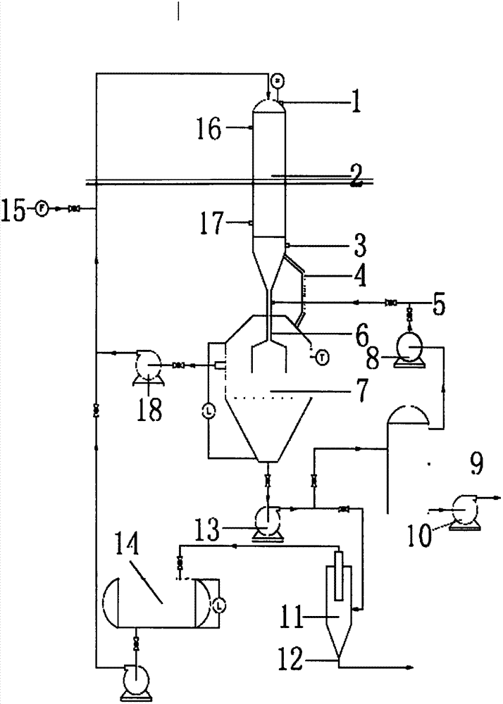
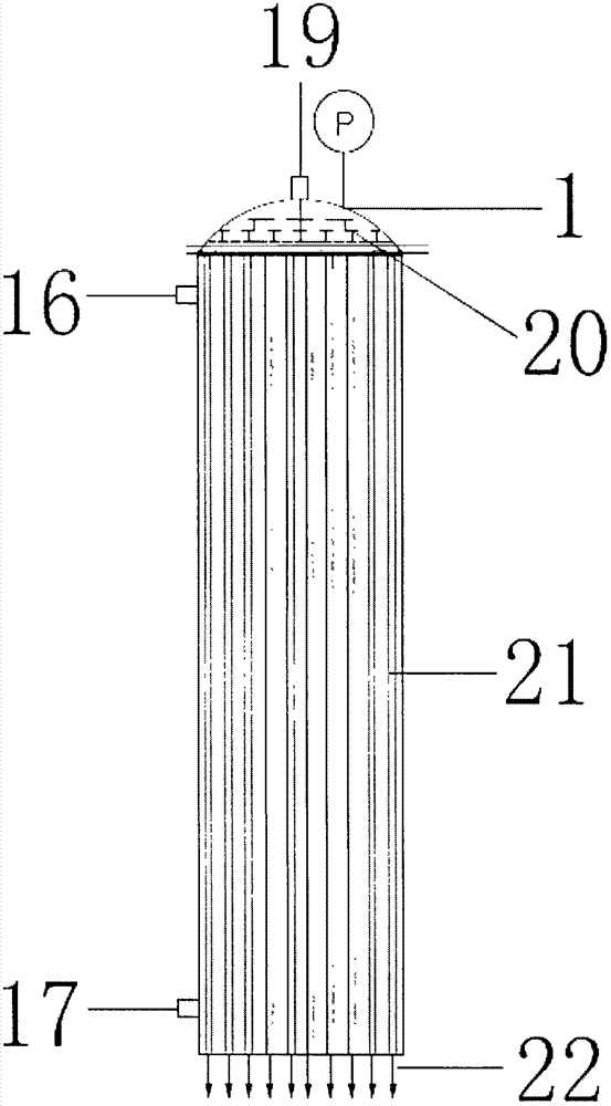
[0021] Such as figure 1 As shown, the device includes a cooler 2, a crystallizer 7, a cyclone 11 and a buffer tank 14, the cooler 2 is provided with a refrigerant liquid outlet 16, a refrigerant liquid inlet 17, and the top is provided with an exhaust port 1, and the cooler 2 It is connected with the crystallizer 7 through a connecting device 6, a delivery pump 13 and a flash tank 9 are arranged between the crystallizer 7 and the cyclone 1, the cyclone 11 is connected with the buffer tank 14, and the cyclone 11 is provided with a solid Material outlet 12, buffer tank 14 is connected with delivery pump and is communicated with cooler 2, is provided with circulation pump 18, waste water source inlet 15 on the pipeline that buffer tank 14 communicates with cooler 2, and circulation pump 18 is connected with crystallizer 7 , the flash tank 9 is provided with a feed pump 10, a vacuum pump 8 is provided between the flash tank 9 and the connector 6, the connector 6 is provided with a...


PUM


Abstract

The invention relates to a method and a device for precipitating salt from salt-containing waste water in sulfonate production, and provides a desalination method and a device with low energy consumption and simple process. Ammonia is dissolved in cooled salt-containing waste water for salt crystallization and precipitation; the salt-containing waste water after salt separation is recycled for cooling and ammonia dissolution; and thus salts are precipitated and separated continuously which allows the waste water to reach the desalination requirements. The device comprises a cooler, a crystallizer, a cyclone separator, and buffer tank; the cooler is provided with a refrigerant fluid outlet, a refrigerant fluid inlet, and an exhaust port at the top; the cooler is connected with the crystallizer through a communicating vessel; a transfer pump and a flash evaporation tank are disposed between the crystallizer and the cyclone separator; the cyclone separator is connected with the buffer tank; the cyclone separator is provided with a solid material outlet. With the above technical scheme, the desalination speed is high, and the efficiency is high. The operation is simple; the automation degree is high; the device maintenance is convenient; and the labor intensity is low. Ammonia in waste water after production can be recovered and recycled, which saves production cost.

Description

technical field [0001] The invention relates to a method and a device for precipitating salt from saline wastewater in sulfonate production. In particular, a desalination method and device for wastewater in petroleum sulfonate production. Background technique [0002] Petroleum sulfonate is an anionic surfactant obtained by sulfonation and neutralization of petroleum distillate oil as raw material. In order to improve the sulfonation conversion rate of raw material oil, it is generally necessary to add an excessive amount of sulfonating agent, so that the neutralized wastewater generally contains A large number of inorganic salt ingredients. Due to the existence of a large amount of inorganic salts, the wastewater cannot be recycled, and direct discharge will not only cause waste of resources but also bring serious environmental pollution problems. For wastewater desalination methods, there are also reports in China, such as CN1074886A provides a method for recycling high-...

Claims


Application Information

Patent Timeline
IPC IPC(8): C02F9/10C02F9/08C02F1/22C02F1/04
CPCY02A20/124
Inventor 杨明常李元新崔继峰肖胜志付兵张小亮
Owner SHANDONG DAMING FINE CHEM CO LTD
Learn More