
Laminate compounding machine

A compound machine and laminating technology, applied in the field of laminating compound machines, can solve the problems that the extrusion device has no horizontal movement ability and up and down lifting ability, cannot cooperate with production well, and the transmission accuracy of the system is not high, so as to achieve flexible horizontal movement The effect of high power, simple structure, and flexible movement of the cutter

Inactive Publication Date: 2015-03-18
常州来义塑料机械有限公司
View PDF6 Cites 0 Cited by
  • Summary
  • Abstract
  • Description
  • Claims
  • Application Information

AI Technical Summary

Problems solved by technology

The existing laminating machine has the following defects: the rewinding and unwinding devices generally rely on the motor, timing pulley and timing belt to drive the machine to work, and the timing belt is severely worn due to long-term work, so it is often necessary to replace it with a new one. Synchronous belt for the normal operation of the machine. The existing winding and unwinding device has the disadvantages of inconvenient replacement of the synchronous belt, low transmission precision of the system, and high noise; the existing extrusion device has no flexible horizontal movement ability and up and down lifting ability. , can not cooperate with the production well; the existing cutter device has the disadvantages of complex structure and insufficient flexibility of the cutter

Method used


Image

  • Laminate compounding machine
  • Laminate compounding machine
  • Laminate compounding machine

Examples


Embodiment Construction

[0061] The preferred embodiments of the present invention will be described in detail below with reference to the accompanying drawings, so that the advantages and features of the present invention can be more easily understood by those skilled in the art, and the protection scope of the present invention can be more clearly defined.

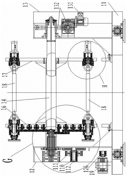
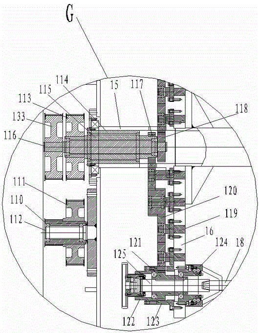
[0062] see Figure 1 to Figure 18 , the embodiments of the present invention include:

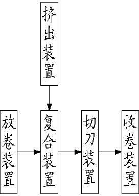
[0063] A laminating machine, comprising:

[0064] Unwinding device for unwinding the base material;

[0065] Extrusion device for providing coating material;

[0066] The compounding device is used for compounding the coating material and the base material;

[0067] Cutter device for trimming or slitting the coated substrate;

[0068] Rewinding device, used to rewind and store the finished base material after trimming or slitting;

[0069] The base material is successively transferred between the unwinding device, the compounding device, the cutter devic...


PUM


Abstract

The invention discloses a laminate compounding machine, which comprises an unreeling device, an extrusion device, a compounding device, a cutting knife device and a reeling device, wherein the unreeling device is used for carrying out material unreeling on base materials, the extrusion device is used for providing laminate materials, the compounding device is used for compounding the laminate materials and the base materials, the cutting knife device is used for carrying out edge cutting or split cutting on the base materials subjected to laminating, the reeling device is used for carrying out reeling and storage on finished product base materials subjected to the edge cutting or split cutting, the base materials are sequentially transferred through transmission rollers arranged on each device among the unreeling device, the compounding device, the cutting knife device and the reeling device, and the extrusion device is arranged at one side of the compounding device and is used for spraying and coating the laminate materials on the base materials. Through adopting the mode, the integral performance of the laminate compounding machine is good, the reeling device and the unreeling device have the advantages that the replacement of the synchronous belt is very convenient, the integral transmission precision is high, and the noise is small; the extrusion device has flexible horizontal moving capability and ascending and descending capability and fully meets the production requirement; and the cutting knife device has the advantages that the structure is simple, the convenience in operation is realized, and the cutting knife is flexible to move.

Description

technical field [0001] The invention relates to the technical field of laminating composite equipment, in particular to a laminating laminating machine. Background technique [0002] The laminating machine is widely used in modern industrial production for laminating processing of paper, cloth and other substrates. The laminating machine mainly includes: unwinding device, extrusion device, compounding device, cutter device and winding device. The existing laminating machine has the following defects: the winding and unwinding devices generally rely on the motor, the synchronous pulley and the synchronous belt to drive the machine to work, and the synchronous belt is worn out due to long-term operation, so it is often necessary to replace it with a new one. Synchronous belt, so that the machine can run normally, the existing rewinding and unwinding device has the disadvantages of inconvenient replacement of the synchronous belt, low system transmission precision, and high no...

Claims


Application Information

Patent Timeline
Patent Type & Authority Patents(China)
IPC IPC(8): B32B37/04B65H16/10B65H18/10F16H1/22B29C47/08B65H35/02
Inventor 刘来义
Owner 常州来义塑料机械有限公司
Learn More