
Special jig fixture for grinding non-standard optical fiber connectors

A technology of optical fiber connectors and molds, applied in the direction of the work carrier, etc., can solve the problems of easy deviation of the grinding angle, low product qualification rate, and low production efficiency, and achieve high production efficiency, high product qualification rate, and compact structure. Effect

Inactive Publication Date: 2013-01-02
黄石晨信光电股份有限公司
View PDF8 Cites 4 Cited by
  • Summary
  • Abstract
  • Description
  • Claims
  • Application Information

AI Technical Summary

Problems solved by technology

[0003] The purpose of the present invention is to solve the problems of precision grinding of non-standard optical fiber connectors by manual clamping, large differences, easy deviation of grinding angle, low product qualification rate and low production efficiency, and provide a non-standard Special jig for optical fiber connector grinding

Method used


Image

  • Special jig fixture for grinding non-standard optical fiber connectors
  • Special jig fixture for grinding non-standard optical fiber connectors
  • Special jig fixture for grinding non-standard optical fiber connectors

Examples


Embodiment Construction

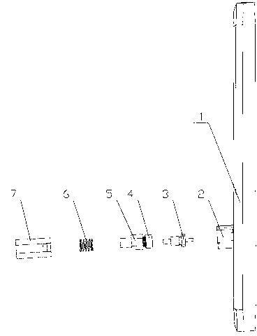
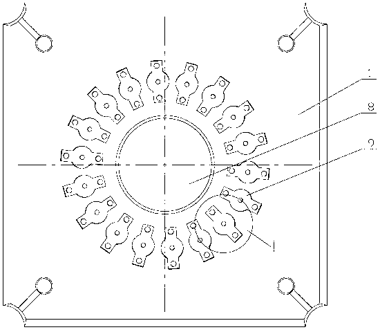
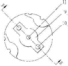
[0018] see Figure 1-9 , the present invention has chuck 1, and the center of chuck 1 is provided with mounting hole 8, particularly: on chuck 1, is designed with some mounting grooves 9 around mounting hole 8 periphery, the bottom surface of mounting groove 9 is inclined surface, and mounting groove The center of 9 is provided with a pin through hole 11, and there are two symmetrically arranged screw holes 10 located on both sides of the pin through 11 hole in the installation groove 9; a seat cover 2 is installed with a screw corresponding to each installation groove 9, so The side wall of the seat cover 2 is provided with two symmetrically arranged axial guide grooves 14, and the bottom of the two guide grooves is provided with a positioning hook groove 15 arranged to rotate in the same direction. The bottom of the seat cover 2 is provided with two symmetrically arranged installation Ears 12, screw holes 13 are opened on each mounting ear 12; a positioning sleeve 7 is equip...


PUM


Abstract

A special jig fixture for grinding non-standard optical fiber connectors comprises a chuck plate. A mounting hole is arranged in the chuck plate. The special jig fixture is characterized in that a plurality of mounting grooves arranged obliquely are arranged on the chuck and encircle the periphery of the mounting hole, pin through holes are arranged in the mounting grooves, a seat sleeve is mounted in each mounting groove by a screw, two axial guide grooves which are arranged symmetrically are arranged on side walls of each seat sleeve, positioning grooves which are rotatably arranged in the same direction are arranged at bottoms of the two guide grooves of each seat sleeve, a positioning sleeve is assembled in each seat sleeve, two axial guiding inner planes are arranged in an inner cavity of each positioning sleeve, springs and elastic chucks are mounted in the positioning sleeves, guiding sections are arranged on the elastic chucks, and guiding outer planes arranged on outer walls of the guiding sections are fittingly connected with the guiding inner planes in the positioning sleeves. The special jig fixture solves problems that the non-standard optical fiber connectors are difficult to grind and machine in the prior art, grinding angles are easy to deviate, production efficiency is low, and the like. The special jig fixture is mainly used for producing and machining the non-standard optical fiber connectors in optical communication.

Description

technical field [0001] The invention relates to a tooling mold for processing optical communication components, in particular to a special tooling fixture for grinding non-standard optical fiber connectors. Background technique [0002] Grinding is the most important part in the production process of optical fiber connectors. The quality of grinding can directly affect the docking performance of optical fiber connectors, including whether the docking is accurate, whether the contact is tight, and the docking performance affects the optical characteristics of the communication line transmission process. Due to the fact that some of the impurity particles that have been ground off are attached to the polishing pad during grinding, there are scratches and broken points on the end faces of some connectors after grinding, which affects the normal operation of the optical fiber transmission line. This kind of optical fiber connector is a substandard product and needs to be reworked...

Claims


Application Information

Patent Timeline
Patent Type & Authority Applications(China)
IPC IPC(8): B24B37/27
Inventor 叶苍竹赵淑明孔祥戴正华官守军
Owner 黄石晨信光电股份有限公司
Learn More